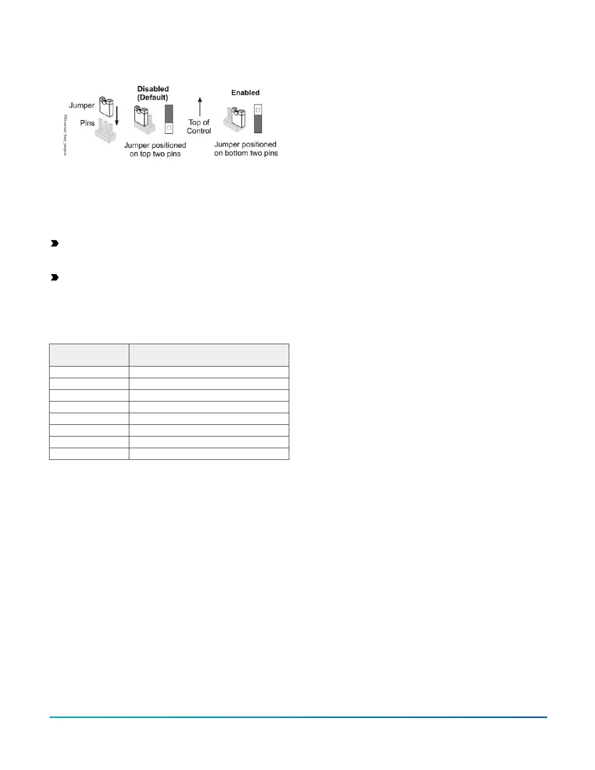
Figure 9: Current loop jumper positions
Setting the current loop jumper to the Enabled position
connects an internal 100 ohms resistor across the UI
terminals, which maintains the 4–20 mA current loop
circuit even when power to the controller is interrupted or
off.
Important: Current loop jumpers must be in the
Disabled (default) position for all UIs that are not set
up to operate as 4–20 mA analog inputs.
Important: A current loop jumper must be in the
Enabled position to maintain a closed 4-20 mA
current loop.
The following table identifies the current loop switches
associated with each UI on the controller.
Table 7: UI Inputs and Jumper Labels
Universal Input
Label
Jumper Label on Circuit Board
IN1 J5
IN2 J6
IN3 J7
IN4 J8
IN5 J9
IN6 J10
IN7 J11
IN8 J12
Input/Output Wiring Validation
The PCA4911 controllers ship with a default state that
can assist in validating the wiring of the input and output
terminals prior to download of an application file. When
the controller is powered on in this state, the Fault LED
will flash in a pattern of two quick blinks and then a long
pause (see Table 8).
To make use of this feature, ensure the rotary switches
are set to the desired controller number and wire the
input and output terminals. Apply power to the PCA
controller and connect to the device with either a MAP
Gateway or FX-DIS1710-0 Local Display to view the
points in the controller. The PCA controller will report
an Operational status even though there is no true
application loaded. CCT will not be able to commission
or upload the device as a result until a true application is
downloaded. The application name displayed will be the
controller number followed by the model of the controller
and “Default State”.
For example, a PCA4911 controller whose rotary switches
are set to 8 would have the default state application name
of “8-PCA4911 Default State”.
The default state creates I/O points for all connections
on the input and output terminals. It assumes all
Universal Inputs (UIs) are Nickel temperature sensors. All
Configurable Outputs (COs) are treated as Binary Outputs
(BOs) with an initial value of 0. The default state also takes
input from a Network Sensor at address 199. If there is
no connected Network Sensor, the startup of this default
state will be delayed by 30 seconds as the controller
attempts to establish connection with the sensor.
Commissioning the controllers
You commission controllers with the CCT software, either
via a ZFR wireless dongle, MAP 4.2+/ BACnet Router
(Mobile Access Portal (MAP) Gateway at version 4.2
or above), or in router mode when connected to an
FX Supervisory Controller. Refer to Controller Tool Help
(LIT-12011147) for detailed information on commissioning
controllers.
Firmware Package File
The FX-FCP-0 equipment controller firmware package files
are required for CCT to configure and commission the
controllers. The firmware package files also allow you to
upgrade an existing PCX to the latest firmware release
available for that expansion module.
Beginning at CCT Release 13, the firmware package files
are orderable separately; they are not included with CCT.
For additional information about the firmware
package files, refer to the CCT Installation Instructions
(LIT-12011259).
Troubleshooting the Controllers
Observe the Status LEDs on the front of the controller
and see the table below to troubleshoot the controller.
To troubleshoot an integral or local controller display,
refer to the FX-DIS Local Controller Display Technical Bulletin
(LIT-12011666).
FX-PCA4911 Advanced Application Controller Installation Guide18