Table 6: Termination details
Type of field
device
Type of Input/
Output
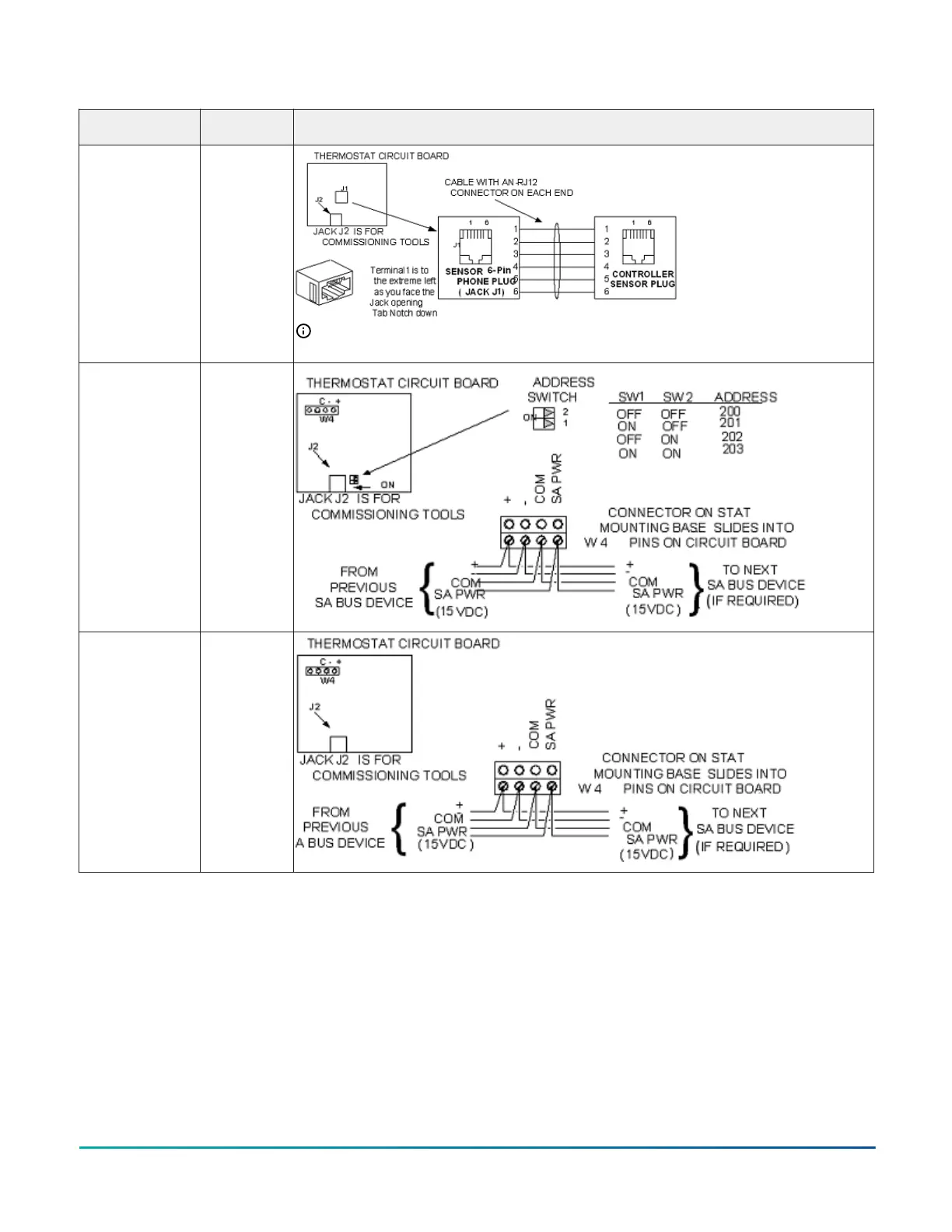
Termination diagrams
Network Stat with
Phone Jack (Fixed
Address = 199)
SA Bus
Note: The bottom jack (J2) on the TE-700 and TE-6x00 Series Sensors is not usable as a zone
bus or an SAB connection.
Network Stat
with Terminals
Addressable
SA Bus
Network Stat with
Terminals (Fixed
Address = 199)
SA Bus
Setup and Adjustments
Setting the Controller Number
Each controller on a network must have a unique number
on the subnet where it resides in order to identify it in
the Controller Configuration Tool (CCT) for uploading,
downloading, and commissioning.
The controller number is set using three rotary switches
(Figure 7) and may be numbered from 000 to 999. The
numbers are ordered from left to right, most significant
bit (MSB) to least significant bit (LSB).
In the following figure the switches are set to 4 2 5,
designating this controller as controller number 425. The
controller number must match the controller number
defined in CCT under Define Hardware > Network
Settings. The number of the controller can be written in
the white squares provided so the controller number can
be easily seen from a distance.
FX-PCA4911 Advanced Application Controller Installation Guide16