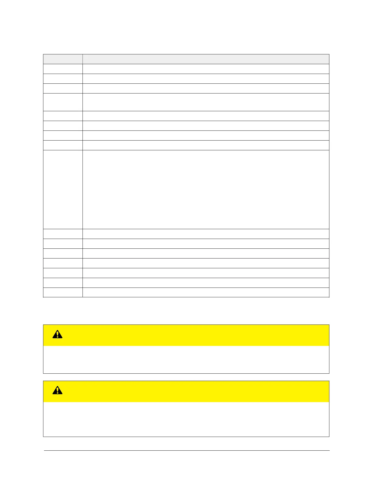
Table 1: FX-PCV1615/1626/1628/1630 Programmable VAV Box feature callout numbers and
descriptions
Callout Physical features: description and references
1 24 VAC, Class 2 Supply Power Terminal Block (see Supply power terminal block)
2 Device Address DIP Switch Block
3 Binary Outputs, 24 VAC Triacs (see Table 3)
4 Configurable Outputs: Voltage Analog Output (0–10 VDC) and Binary Output (24 VAC
Triac) FX-PCV1630, 1626, and 1628 only) (see Table 3)
5 Dual Port Fitting
6 Manual Override Button (see Mounting)
7 Coupler Bolt (see Mounting)
8 Controller Coupler (see Mounting)
9 Universal Input: Voltage Analog Input (0–10 VDC)
Resistive Analog Inputs (0–600k ohm) (see Table 3):
0–2k Potentiometer
RTD: 1k Nickel, 1k Platinum, or A99B SI
NTC: 10K Type L (10K Johnson Controls
®
Type II is equivalent to Type L) or 2.252K
Type II
Dry Contact Binary Input
10 FC Bus Terminal Block. May also be used for N2 connections.
11 EOL (End-of-Line) Switch (see Setting the EOL switch)
12 SA Bus Terminal Block
13 Modular Port (FC Bus) RJ-12 6-Pin Modular Jack (see Modular ports)
14 Modular Port (SA Bus) RJ-12 6-Pin Modular Jack (see Modular ports)
15 Captive Spacer and Screw
16 LED Status Indicators (see Table 8)
Wiring
CAUTION
Risk of Electric Shock
Disconnect the power supply before making electrical connections to avoid electric shock.
CAUTION
Risque de décharge électrique
Débrancher l'alimentation avant de réaliser tout raccordement électrique afin d'éviter tout risque de
décharge électrique.
FX-PCV1615/1626/1628/1630 Programmable VAV Box Controllers Installation Instructions6