10
P00792Q-rev.2
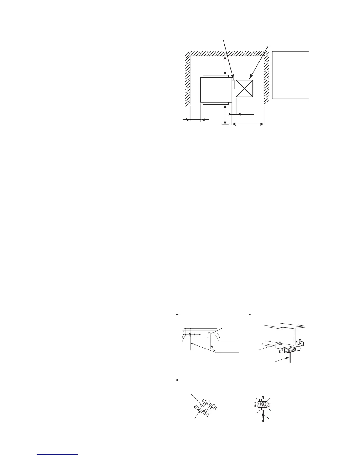
4. Installation Location
Figure. 4.1 Operation and Installation Space
(1) Install the indoor unit, allowing for proper
clearance for operation and maintenance
access, as shown in Figure. 4.1.
Rear Side
Min. 39-3/8
(1000)
Service Access Door
(Min
□
17-11/16 (450))
In case that the
ceiling board can
not be detected
for servicing,
prepare a service
access door
below the indoor
unit for removing
the indoor unit.
Min. 39-3/8
(1000)
Min. 23-5/8
(600)
(2) Consider the air distribution from the indoor unit to the space of the room, and select a suitable location
so that uniform air temperature in the room can be obtained.
(3) Do not leave combustible materials inside the service space of the indoor unit.
(4) Avoid obstacles which may hamper the air intake or the air discharge ow.
(5) Do not install the indoor unit in a machine shop or kitchen where vapor from oil or its mist ows to the
indoor unit.
The oil will deposit on the heat exchanger, thereby reducing the indoor unit performance, and may
deform and in the worst case, break the plastic parts of the indoor unit.
(6) Pay attention to the following points when the indoor unit is installed in a hospital or other facilities
where there are electronic waves from medical equipment.
(a) Do not install the indoor unit where the electromagnetic wave is directly radiated to the electrical
box, communication cable or wired controller.
(b) Install the indoor unit and components as far away as practical or at least 9.8ft (3m) from any
electromagnetic wave radiator.
(c) Prepare a steel box and install the wired controller in it. Prepare a steel conduit tube and wire the
controller cable in it. Then, connect the ground wiring with the box and the tube.
(d) Install a noise lter when the power supply emits harmful noises.
(7) To avoid any corrosive action to the heat exchangers, do not install the indoor unit in an acid or alkaline
environment.
5. Installation Work
5.1 Suspension Bolts
(1) Determine the nal location and installation
orientation of the indoor unit with respect
to the space allowed for piping, wiring, and
maintenance access.
(2) Mount suspension bolts, as shown in Figure
5.1.
5-7/8 to 6-5/16
Insert
(221 to 331 lbs)
I Beam
 Loading...

