P00792Q-rev.2
21
8.2 Electrical Wiring Capacity
8.2.1 Field Minimum Wire Sizes for Power Supply
•
This equipment can be installed with a Ground Fault Circuit Interrupter (GFCI), which is a recognized
measure for added protection to a properly grounded unit. Install appropriate sized breakers /
fuses / overcurrent protection switches and wiring in accordance to local, state and NEC codes and
requirements. The equipment installer is responsible for understanding and abiding by applicable codes
and requirements. Failure to use a GFCI can result in electrical shock or re.
•
Do not operate the system until all the check points have been cleared.
(A) Verify that electrical resistance is more than one megaohm by measuring the resistance between
ground and the terminals of the various electrical components. If less than one megaohm, do not
activate the system until the electrical current drain is found and repaired.
(B) Check to ensure that the stop valves for the outdoor unit are fully opened, and then start the system.
(C) Check to see that the main power has been switched ON for longer than 12 hours prior activating
the system. Power to the crankcase heater needs this time interval to warm the compressor oil up to
operating temperature.
•
Do not touch any of the parts by hand at the discharge gas side, since the compressor chamber and the
pipes at the discharge side are heated higher than 194
o
F (90
o
C).
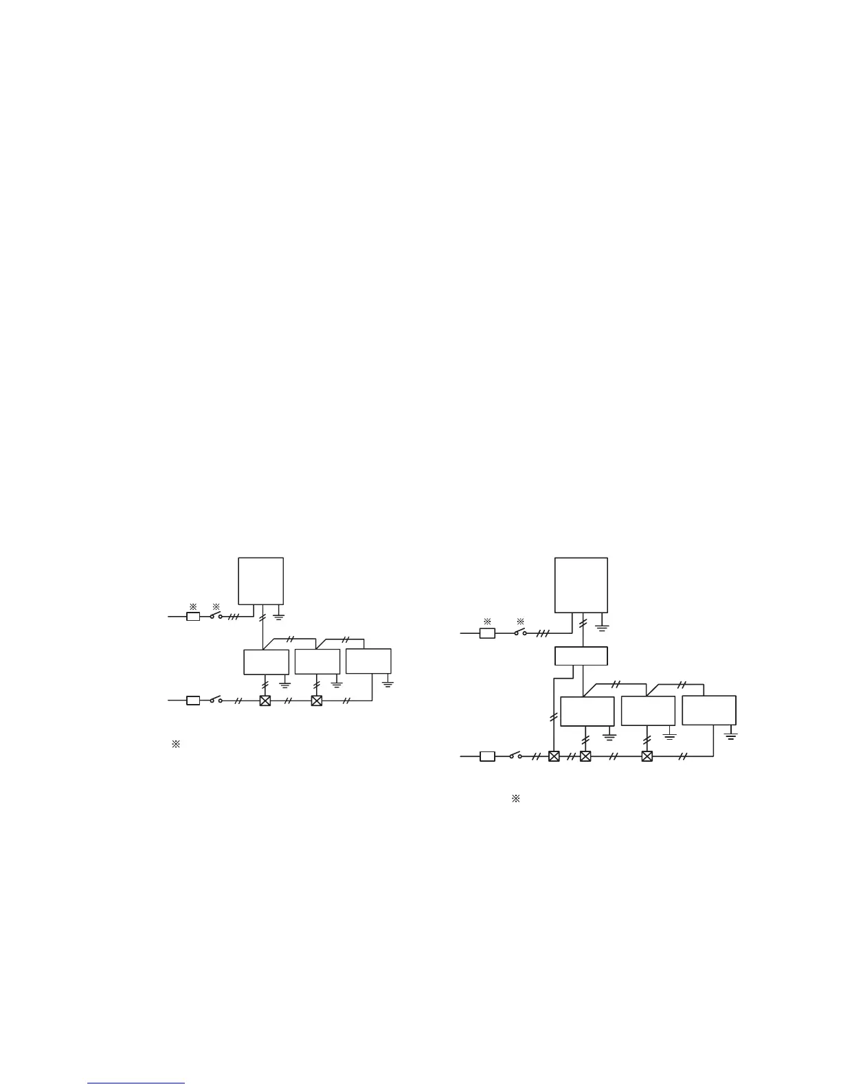
<HeatPumpSystem> <HeatRecoverySystem>
8.2.2 Details of Electrical Wiring Connection
The electrical wiring capacity of the outdoor unit should be referred according to the "Installation and
Maintenance Manual" for the outdoor unit. Adjusting the DIP switches may be required depending on the
arrangement with the outdoor unit.
Select wiring capacity according to the table 8.1. Install a GFCI (Ground Fault Circuit Interrupter) and
main switch as shown in each of the system diagrams below.
Outdoor
Unit
Indoor
Unit
Switchbox
 Loading...

