P00792Q-rev.2
27
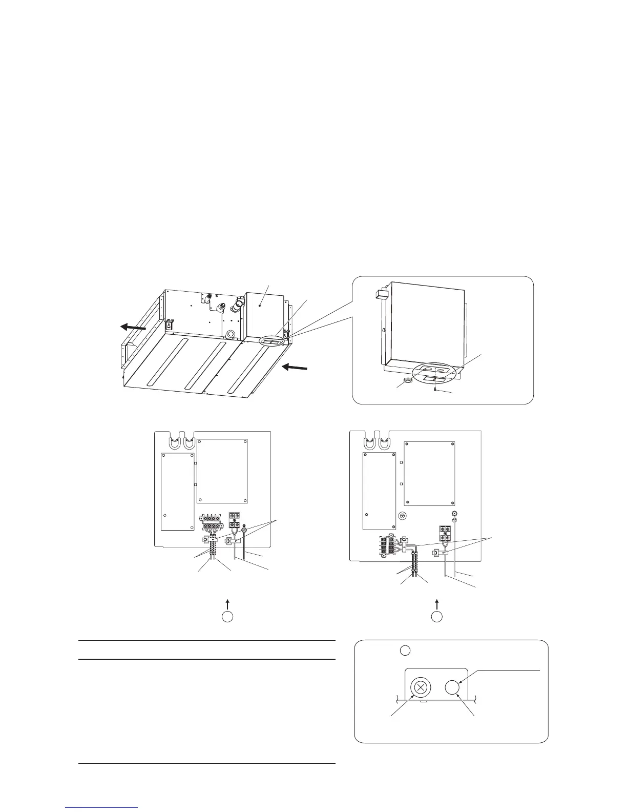
8.4 Wiring Connection
(1) Remove the connecting hole cover of the electrical box and install the rubber bush (Accessory) to the
connecting hole for communication cable.
(2) Pass the communication cable and the wired controller cable through the connecting hole for
communication cable.
Connect the communication cable to the terminals 1, 2 of TB2 inside the electrical box.
Connect the wired controller cable to the terminals A, B of TB2 inside the electrical box.
(3) Pass the power supply wiring and the ground wiring through the connecting hole for power supply
wiring.
Connect the power supply wiring to the terminals L1, L2 of TB1 inside the electrical box.
Connect the ground wiring to the ground terminal inside the electrical box.
(When connecting the power supply wiring and the ground wiring outside of the unit, run through the
conduit tube.)
(4) Tightly clamp the power supply wiring, the ground wiring, the wired controller cable and the
communication cable utilizing the cable band.
Wired Controller
Cable
Power Supply
Wiring
Ground Wiring
Communication
Cable
Cable Band
(H,Y,C)IDM006 - 018B21S (H,Y,C)IDM024 - 048B21S
Connecting Hole
Connecting Hole
Cover
(After install,
unnecessary)
Remove the fixing screw.
Rubber Bush
(Accessory)
•
Insert the communication cables and wired controller
cable into the PVC tube “VW-1 600V” (Accessory) to
separate them from the power supply wirings in the
indoor unit.
•
Fix the both ends of the PVC tube by cable clamp
(Accessory).
•
If shielded cable is used, terminate at the ground
terminal.
NOTE
 Loading...

