Table 9: Suction, ambient, coil, and discharge sensors
T [ ℃ ] Rmin [ KΩ ] Rnom [ KΩ ] Rmax [ KΩ ] Dev(MIN)% Dev(MAX)%
-30 60.78 64.77 68.99 -6.16 6.12
-15 29.07 29.97 30.89 -3.00 2.98
0 14.70 15.00 15.29 -2.00 1.90
15 7.804 8.021 8.240 -2.71 2.66
30 4.355 4.550 4.753 -4.29 4.27
45 2.558 2.701 2.850 -5.29 5.23
60 1.551 1.654 1.762 -6.23 6.13
75 0.9676 1.041 1.120 -7.05 7.05
90 0.6188 0.6718 0.7291 -7.89 7.86
105 0.4056 0.4440 0.4859 -8.65 8.62
Troubleshooting
Variable capacity systems can be difficult to troubleshoot
considering integrated fault isolation and protection
algorithms. When the HP system is not operating within
acceptable parameters or there is a need to verify system
or component operation, it may be necessary to perform
specific system checks. Follow the troubleshooting steps,
component checks, and fault code/resolution tables in
this section to isolate potential root causes.
Checking components
Check the refrigerant system.
Test system flow
Conditions:
• The compressor is running.
• The outdoor section is installed in a well-ventilated
area.
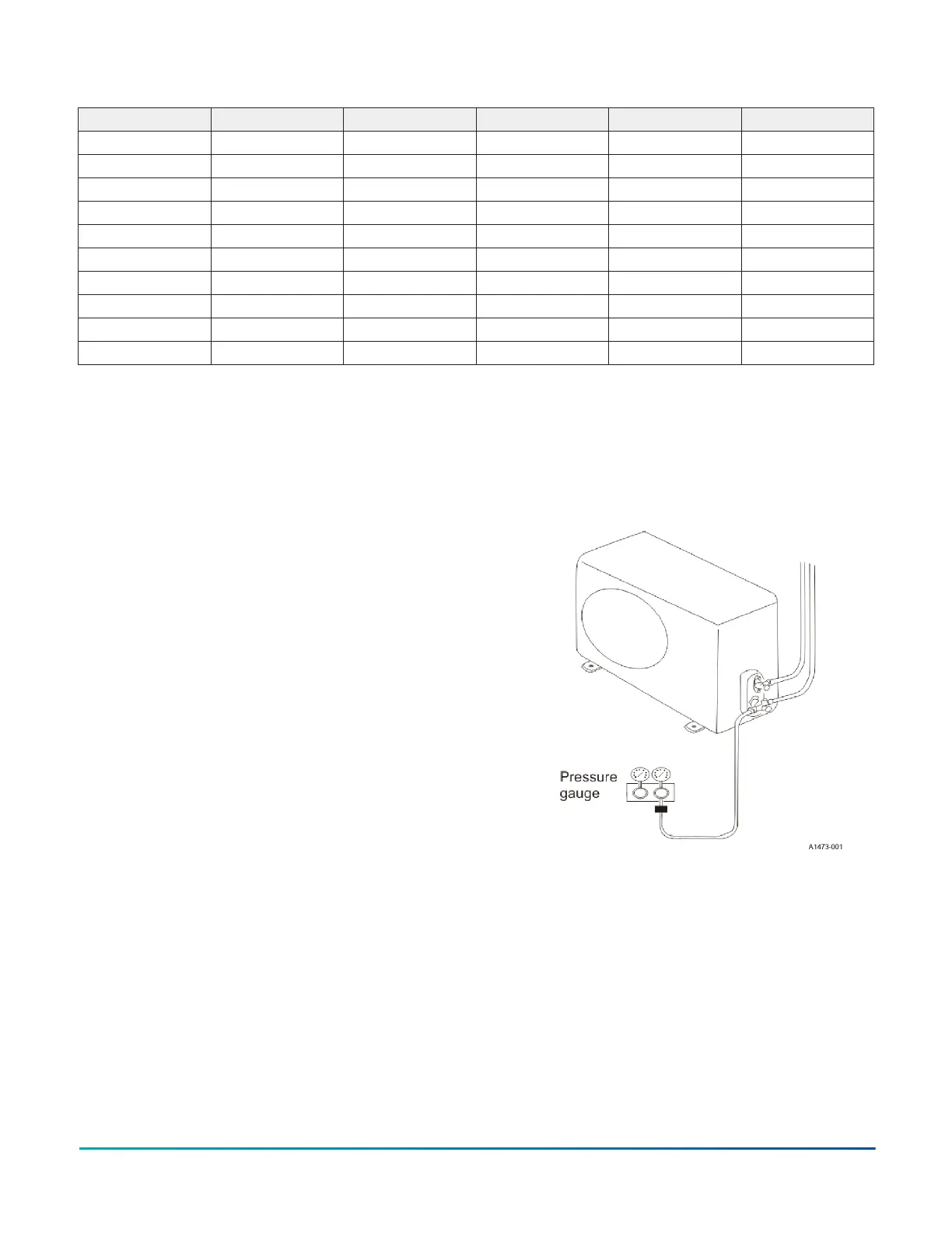
Tool
Pressure gauge:
• See: Tube defrost
• Feel: The difference between the tube's temperature
• Test: Test pressure
Figure 37: Refrigerant system
Installation Manual: HMH7 Series - 17 SEER Horizontal Discharge Modulating Heat Pump32
Johnson Controls Ducted Systems