Wall mount installation
Ensure to mount the outdoor unit on a solid base that
is sloped to shed water, secure from settlement, and
isolated from the structural foundation or walls to prevent
sound and vibration transmission into the living space.
On occasion, site conditions may require the use of
direct wall mounted brackets to locate and support the
outdoor unit. In these applications, ensure to address unit
base pan support, structural integrity, safe access and
serviceability, as well as the possible sound and vibration
transmission into the structure. Wall mounting requires
three mounting brackets and is best served by a properly
engineered solution. Refer to the Price Pages for the
specific part number for your application.
Avoid the following places for installation where damage
to the outdoor section may occur:
• Where there is machine oil
• Coastal regions where the equipment is prone to
atmospheric corrosion
• Near hot springs where the equipment is prone to
sulfide gas corrosion
• In proximity to high-frequency or wireless
equipment
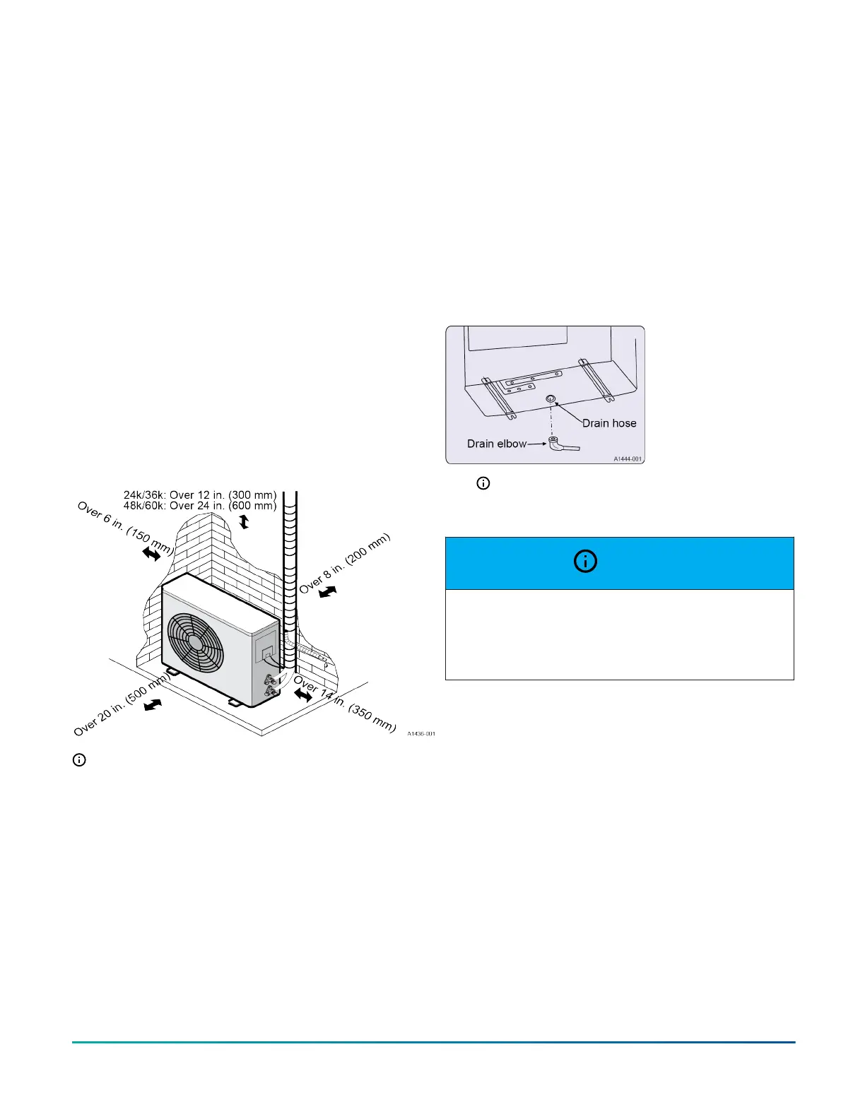
Figure 6: Minimum clearances when selecting a
location
Note: When operating the outdoor section in low
ambient conditions, follow these instructions:
• Never install the outdoor unit in a place where
its air inlet/outlet side may be exposed directly
to wind.
• To prevent exposure to wind, install the
outdoor unit with its air inlet side facing the
wall.
• To prevent exposure to wind, install a baffle
board on the air outlet side of the outdoor unit.
Installing the drain elbow and drain
hose
About this task:
Condensate water may drain from the outdoor unit when
the unit operates in heating mode. To avoid adverse
conditions in the area around the unit, install the included
drain elbow and a drain hose to drain out the condensate
water. Install the drain elbow and drain the hose before
the indoor and outdoor units are connected.
1. Connect the drain hose (field-supplied, 15 mm
inside diameter) as shown in Figure 7.
Figure 7: Drainage
Note: Do not use a drainage elbow in colder
climates. The drain may freeze and cause the
fan to stop running.
NOTICE
Heat pumps defrost periodically resulting in water
drainage. The unit must not be located where
water drainage may freeze and create a hazardous
condition, such as sidewalks and steps.
Installation Manual: HMH7 Series - 17 SEER Horizontal Discharge Modulating Heat Pump 9
Johnson Controls Ducted Systems