Figure 11: Brand label location
Precautions for brazing of lines
All outdoor unit and indoor coil connections are copper-
to-copper and must be brazed with a phosphorous-
copper alloy material such as Silfos-5 or equivalent. Do
not use soft solder. The outdoor units have reusable
service valves on both the liquid and vapor connections.
The total system refrigerant charge is retained within
the outdoor unit during shipping and installation. The
reusable service valves are provided to evacuate and
charge per this instruction. Serious service problems can
be avoided by taking adequate precautions to ensure an
internally clean and dry system.
CAUTION
The indoor coil is under inert gas pressure. Relieve
pressure from the coil by depressing the Schrader
core at the end of the suction manifold stub out. Dry
nitrogen must always be supplied through the tubing
while it is being brazed because the temperature
required is high enough to cause oxidation of the
copper, unless an inert atmosphere is provided.
The flow of dry nitrogen must continue until the joint
cools. Always use a pressure regulator and safety
valve to insure that only low pressure dry nitrogen
is introduced into the tubing. Only a small flow is
necessary to displace air and prevent oxidation.
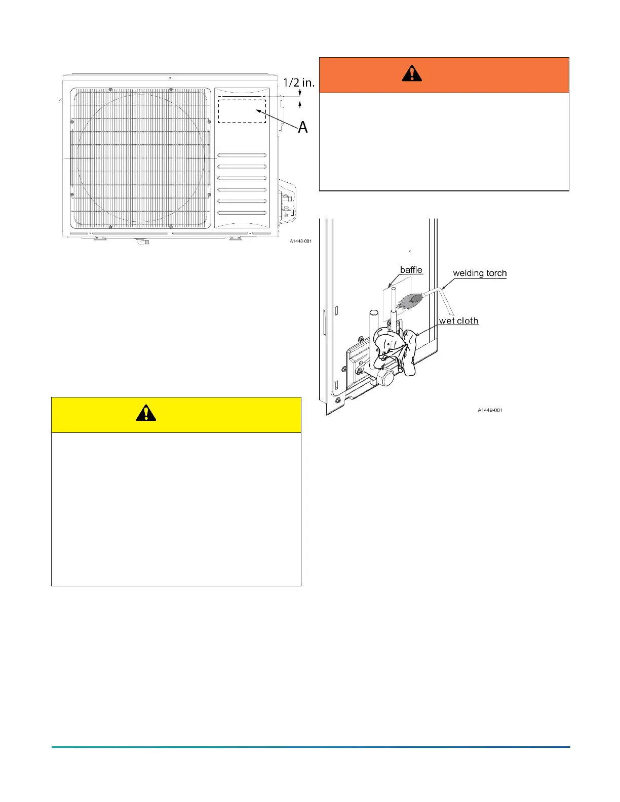
Precautions for brazing of the service valve
• Wrap a wet rag around the service valve to prevent
heat damage, as shown in Figure 12.
• Protect all painted surfaces, insulation, and plastic
base during brazing.
• After brazing, cool the joint with a wet rag.
WARNING
This is not a backseating valve. The service access
port has a valve core. Opening or closing the valve
does not close the service access port. If the valve
stem is backed out past the chamfered retaining
wall, the O-ring can be damaged, causing leakage or
system pressure that could force the valve stem out of
the valve body, possibly causing personal injury.
Figure 12: Brazing the service valve
Connecting the refrigerant lines
About this task:
The valve can be opened by removing the plunger cap
and fully inserting a hex wrench into the stem, then
backing out counter-clockwise until the valve stem just
touches the chamfered retaining wall.
1. Remove the cap and Schrader core from both the
liquid and vapor service valve service ports at the
outdoor unit. Connect low pressure nitrogen to the
liquid line service port.
2. Braze the liquid line to the liquid valve at the
outdoor unit. Ensure to wrap the valve body with a
wet rag. Allow the nitrogen to continue flowing.
3. Carefully remove the plugs from the liquid and
vapor connections at the indoor coil.
4. Braze the liquid line to the indoor coil liquid
connection. Nitrogen should be flowing through
the indoor coil.
5. Slide the grommet away from the vapor connection
at the indoor coil. Braze the vapor line to the
indoor coil vapor connection. After the connection
has cooled, slide the grommet back into original
position.
Installation Manual: HMH7 Series - 17 SEER Horizontal Discharge Modulating Heat Pump 11
Johnson Controls Ducted Systems