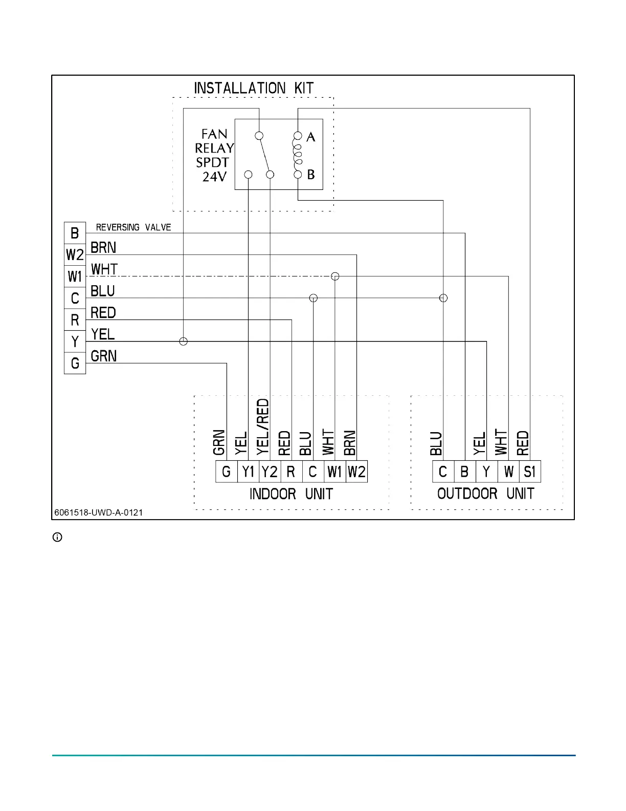
Figure 14: Wiring diagram - HMH7 ACC VS ECM
Note:
• Use the B terminal on the thermostat for the reversing valve connection (energized in heat mode).
• The room thermostat must control fossil fuel operation if matched with a gas furnace.
• Refer to wiring and installation kit HMH7AK001 for additional wiring detail on the indoor unit.
Connecting HMH72B24 and HMH72B36
wiring
About this task:
Connect wiring to the unit by completing the following
steps.
1. Unscrew the mounting screws to remove the
electric box cover.
2. Fasten the power supply cable and the low-voltage
cable to the conduit holder using the lock nut.
3. Connect the power supply cable and the low-
voltage cable to the terminal.
4. Fasten the power supply cable and the low-voltage
cable with the cable clamp.
5. Make sure to seal any holes when wiring is
complete. Place the cables side to side (do not
overlap the cables).
6. Re-install the electric box cover when wiring is
complete.
Installation Manual: HMH7 Series - 17 SEER Horizontal Discharge Modulating Heat Pump 15
Johnson Controls Ducted Systems