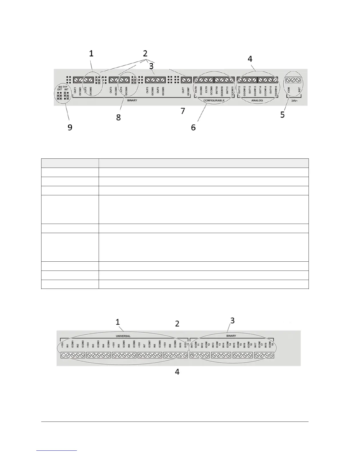
Figure 11: NCE25 series output terminal blocks, Binary output jumpers,
and supply power terminal block as viewed from the top of an NCE25
Table 10: Call-out table for NCE25 series output terminal blocks, binary output jumpers, and supply
power terminal block as viewed from the top of an NCE25
Callout Description
1 Binary output - Two jumpers positioned for an internal source of power.
2 Binary outputs are 24 VAC Triac outputs.
3 Back of NCE (Flush to mounting surface).
4 Analog outputs can be defined as:
• Voltage Analog outputs (0-10 VDC)
• Current Analog outputs (4-20 mA)
5 24 VAC, Class 2 supply power terminal block. The center terminal is not used.
6 Configurable outputs can be defined as the following:
• Voltage Analog outputs (0-10 VDC)
• Binary outputs (24 VAC Triac)
7 Front of NCE.
8 Binary output - Four jumpers positioned for an external source of power.
9 Required jumper positons for setting a Binary output's power source.
Figure 12: Universal input and Binary input terminal
blocks as viewed from the bottom of an NCE25
19NCE25 Installation Instructions

 Loading...


