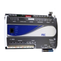
VAV Controller—Variable Air Volume (VAV) Controller 25
30F31F32FWiring Details
Take special precautions and follow certain grounding procedures when
installing the VAV Controller.
!
CAUTION: Possible Equipment Damage or Electrical Shock.
To avoid damaging equipment or possible electrical
shock, ensure that all power supplies to the system
have been disconnected prior to wiring installation.
The CMOS (Complimentary Metal Oxide
Semiconductor) circuits used in the controller are
static sensitive. Use static protection (anti-static mats
and/or grounding straps) when working on or near
internal circuitry.
Follow these precautions:
z Make all wiring connections in accordance with the National Electrical
Code (NEC) as well as within local regulations.
z Locate equipment and route the wiring so that signal wiring is twisted
pair, and separated from power wiring to the maximum extent possible.
To establish tight, reliable electrical connections, use the correct wire
sizes for the terminals.
z Make all wiring connections to the VAV Controller using only copper
conductors.
z The N2 must be daisy-chained. The use of Y or T connections without a
repeater installed in the T tap may cause loss of communications.
z Do not run N2 Bus, Zone Bus, Analog Input (AI), Binary Input (BI), or
Binary Output (BO) wiring in the same conduit as line voltage wiring
(above 30 VAC), or with wiring that switches power to highly inductive
loads such as contactors, coils, motors, or generators.
z Do not run non-shielded N2 Bus wiring in the same conduit or bundle as
24 VAC power wiring.
z You may run Zone Bus, Analog Input, Analog Output, and Binary Input
wiring in the same bundle or conduit where convenient. If the Binary
Output wiring is not wired through other switches or contacts, you may
also bundle it with the other I/O wiring where convenient.

 Loading...


