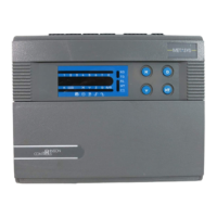
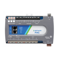
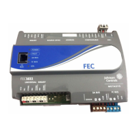
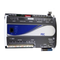
38 VAV Controller—Variable Air Volume Controller
There are four dry contact binary inputs on the controller. They are located
in the center of the terminal strip. The VAV Controllers have an available
momentary binary input option. This input is connected at the zone sensor
input to initiate a temporary occupancy or boost mode of operation.
The binary inputs on the VAV Controllers are inactive when open. They
are active when a contact closure to BI Common is applied. BI 4 may be
used as an accumulator input for frequencies less than 100 Hz.
There are six or eight binary outputs (depending on the selected model) on
the controller. Binary outputs are triacs on the controller hardware. These
outputs switch the transformer’s low side (or common) to the output.
Each binary output must be connected between the BO terminal and
24 VAC terminal since it is low side switching.
IMPORTANT: Chattering Relays Driven by Binary Outputs.
Chattering may occasionally occur in relays from
manufacturers other than Johnson Controls due to a
low load condition across the binary output triac. The
chattering relays are audible, and arcing may be visible
at the contacts.
The minimum holding current for the triac is 50 mA.
To eliminate chattering, use a 360 ohm, 5W resistor
across the binary output, or use the AS-RLY100-1
Relay Kit.
There have been a few instances where loads have met
the 50 mA current requirement, but still chattered. To
date, the exceptions are Honeywell damper actuator
(Model ML6161) and Finder relay (Model 60.12). In
these instances we recommend a
1000 ohm, 2W resistor in parallel across the load.
There are two analog outputs on the VAV101, VAV111, and VAV141
Controller. The load is connected between the analog output and analog
output common terminals. Each output is controlled to generate a
proportional voltage output of 0 to 10 VDC to common. The maximum
load for each output is 10 mA with a minimum load resistance of
1000 ohm.
48F49F50FBinary Inputs
51F52F53FBinary Outputs
54F55F56FAnalog Outputs

 Loading...


