26 VAV Controller—Variable Air Volume Controller
Use a separate isolation transformer or step-down transformer for each
VAV Controller. Refer to Standards Compliance in the Introduction
section of this technical bulletin. The power transformer used must comply
with:
z CSA 22.2 No. 205
z NEMA ICS 2, Part 2, 230
Limit the power to each VAV to 3 amperes or less. However, if you use
one low voltage power trunk to power multiple controllers, follow these
precautions:
z Ensure polarity is maintained at each 24 VAC connection.
z As per NEC code, you must enclose 24 VAC power trunks with
greater than 4 amperes (100 VA) in conduit.
Note: See NEC Article 725/Class 2 (30 VRMS Max) and (100 VA Max).
Any individual binary output (triac) can drive up to 800 mA when you
limit the total 24 VAC power draw. You must limit the power draw of a
controller and its load to avoid heat dissipation problems. You must limit
the total 24 VAC power draw of a VAV Controller installed in an
enclosure to a maximum of 40 VA. You must limit the total 24 VAC
power draw of a VAV Controller mounted in an open air environment to a
maximum of 75 VA.
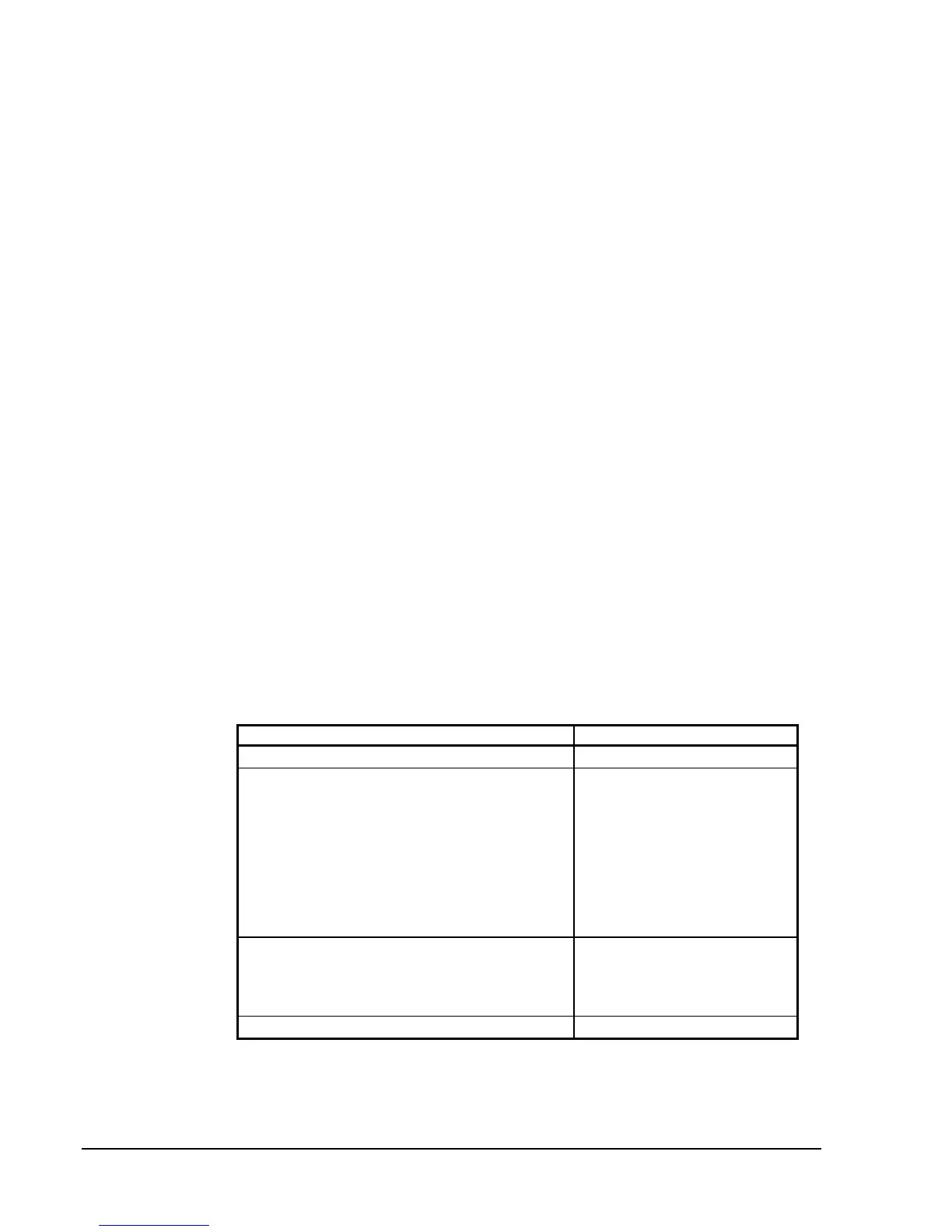
When you determine the system load, consider all the actual loads as well
as the basic load of the controller. The following tables assist you in
determining the total 24 VAC power draw of your system.
Table 4: VAV Power and Load Specifications
System Loads Power Draw
VAV Controller with sensors/transmitters 10 VA (400 mA)
BO Load
Relay, Contactor, Solenoid, Incremental Actuator*
Maximum allowable load for any individual binary output
(triac) is 19 VA** (800 mA at 24 VAC)
Minimum required load for each binary output (triac)
used is 1.2 VA (50 mA at 24 VAC)
Note: Relay loads less than 50 mA may cause
triac/relay chattering. If necessary, use a
1000 ohm 2W resistor across the binary output.
Refer to specific product
documentation.
AO Load
Actuator
Maximum allowable load for each AO is 10 mA with a
minimum load resistance of 1000 ohm.
Refer to Table 5.
Zone Terminal or CBLPRO 1.2 VA (50 mA)
*Actuator VA requirements are found in Table 5.
**With total controller power draw limited as described previously.
Power Source
and Loads
 Loading...


