VAV Controller—Variable Air Volume (VAV) Controller 37
The VAV Controller has two sets of DIP switches. One set is for
configuring the analog input points, and the other for setting the address of
the controller. Use Tables 9 and 10 to set the SW1 and SW2 analog input
DIP switches.
Refer to the Networking the Controller section of this technical bulletin for
instructions on setting the N2 address DIP switches.
ANALOG INPUTS
COMMON
aiswtch
ANALO
V
T
2V
10V
SW1
SW2
1 2 3 4 5 6
O
N
1 2 3 4 5 6
O
N
ARY IN
BI NARY OUTPUTS
BINARY INPUT
ANALOG INPUTS
1 2 3 4 5 6 1 2 3 4
TO
ZONE
STAT
BINARY OUTPUT
1 2 3 4 5 6
24 VAC
COMMON
24 VAC
COMMON
ANA OUT
ANALOG
OUTPUT
1 2
BI NARY COM
24 VAC
COMMON
24 VAC
COMMON
R
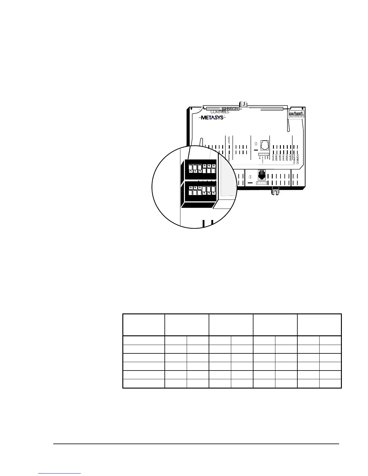
Analog Input Switches
Figure 13: Setting the Analog Input DIP Switches
The AI switches are factory set with AI 1, 2, and 3 as resistive inputs and
AI 4, 5, and 6 as 0 to 10 VDC inputs. However, you may configure them
to any combination. Use the following table to set the switches. For
example, if you connect a 10 VDC input to AI 4, set SW1-4 to Off and
SW2-4 to On.
Table 10: Analog Input DIP Switch Settings
Hardware
Point
Switch
Temperature
(Resistive
Input)
2 VDC
(0 to 2 VDC
Input)
10 VDC
(0 to 10 VDC
Input)
AI 1
SW1-1 SW2-1 ON OFF OFF OFF OFF ON
AI 2
SW1-2 SW2-2 ON OFF OFF OFF OFF ON
AI 3
SW1-3 SW2-3 ON OFF OFF OFF OFF ON
AI 4
SW1-4 SW2-4 ON OFF OFF OFF OFF ON
AI 5
SW1-5 SW2-5 ON OFF OFF OFF OFF ON
AI 6
SW1-6 SW2-6 ON OFF OFF OFF OFF ON
 Loading...


