46 VAV Controller—Variable Air Volume Controller
Set the N2 address and test for N2 voltage, polarity, and isolation before
actually wiring the VAV Controller for operation. Refer to the ASC and
N2 Bus Networking and Troubleshooting Guide
(LIT-6363003) in the Application Specific Controllers Technical Manual
(FAN 636.3) for more information.
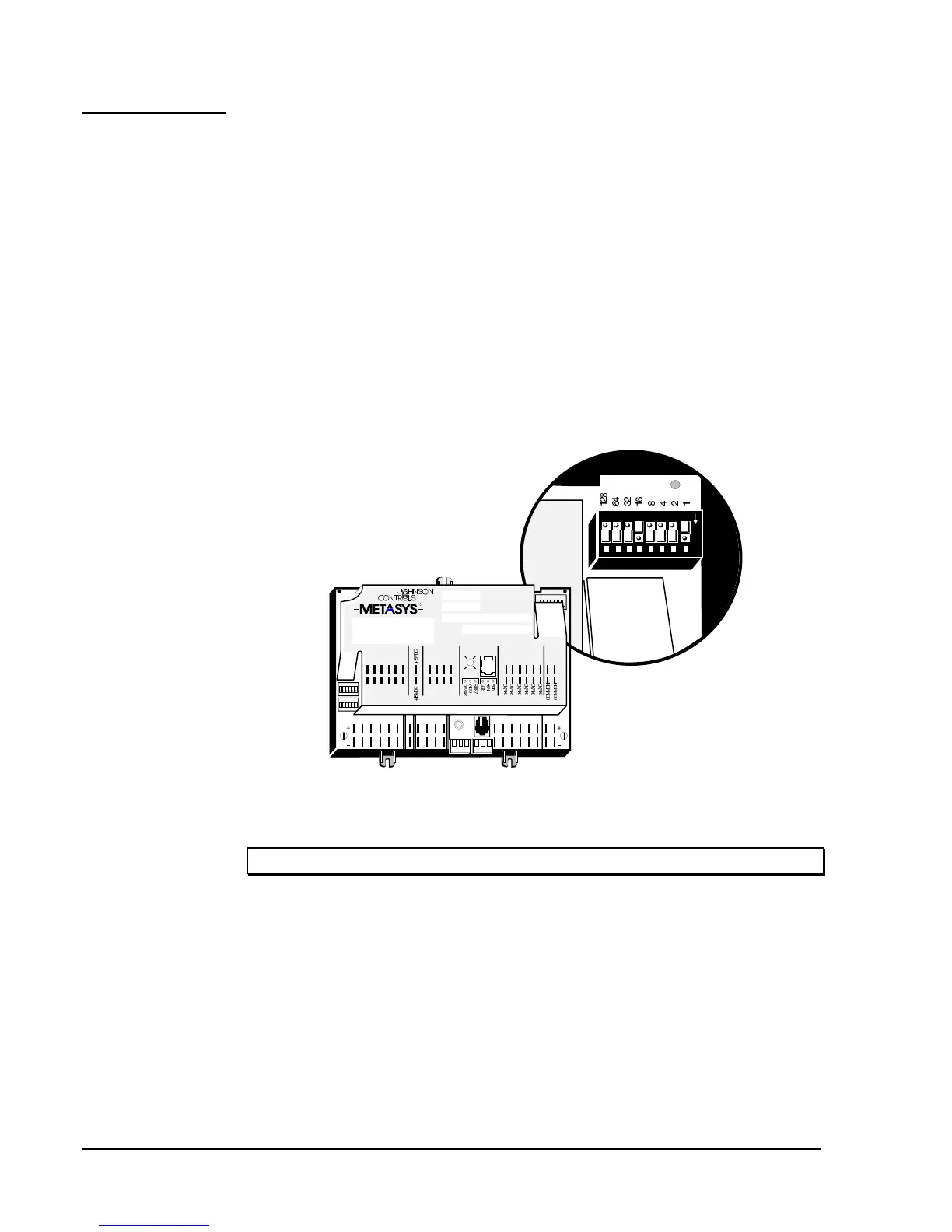
The switches located in the upper right corner of the VAV are set to the
same number as was assigned to the module through software. The
Metasys (or Companion) Facility Management System (FMS) uses this
address for polling and commanding. The numbers are in binary format
and vertically arranged with the least significant digit to the right.
For example, if the controller address is 17 (decimal), the binary
representation is 00010001–Switches 1 and 16 must be set to the On
position (1 + 16 = 17), as shown in Figure 19.
dipswtch
Address Switches
N
O
1 2 3 4 5 6
OFF
1 2 3 4 5 6 7 8
BINA RY INANALOG INPUTS BINARY OUTPUTS
BINARY INPUT
ANALOG INPUTS
1 2 3 4 5 6 1 2 3 4
ANALOG INPUTS
COMMON
TO
ZONE
STAT
BINARY OUTPUT
1 2 3 4 5 6
Z BUS
DSI
P5 P 6
1 2 3 4 5 6
ANA OUT
ANALOG
OUTPUT
1 2
BINARY COM
R
Figure 19: Setting the N2 Address DIP Switches
IMPORTANT: When setting the N2 Address, do not use address “0.”
66F67F68FInstalling the
N2 Bus
Setting the N2
Address
 Loading...


