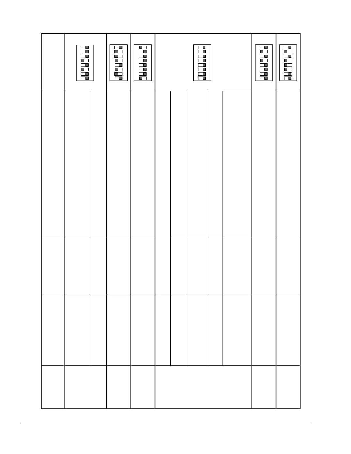
Table 2: LED Flash Sequences, Setup Values, Mode Settings on DIP Switch Block and Default Values and Mode Settings Example
Release
Push Button
After...
Value/Mode Name
(Binary Switch Number)
Value Range/Mode
Settings (Example
Default Settings)
Switch Number and Position
Description of Value/Setting
DIP Switch Block
Example Default
Settings
Two Flashes Low Speed Mode
(Switch 128)
Settings: ON or Off
(Default Setting:
Off
)
Switch 128 Off = No voltage to motor when sensed pressure is
below start pressure.
Switch 128 ON = Start voltage to motor when sensed pressure is
at or below start pressure.
Start Voltage Value
(Switches 1 to 64)
Value Range: 10 to 90
(Default Value:
40
)
Position Switches 1 to 64 ON or Off so that the sum of the
switches set to ON equals the Start Voltage Value.
Three Flashes Start Pressure Value
(Switches 1 to 128)
Value Range: 10 to 230
(Default Value:
110
)
Position Switches 1 to 128 ON or Off so that the sum of the
switches set to ON equals the Start Pressure Value.
Four Flashes End Pressure Value
(Switches 1 to 128)
Value Range: [Start
Pressure + 8] to 240
(Default Value:
129
)
Position the Switches 1 to 128 ON or Off so that the sum of the
switches set to ON equals the End Pressure Value.
Five Flashes
(Switches 64 and
128 Off)
Split Winding Mode
(Switch 32)
Settings: ON or Off
(Default Setting:
Off
)
Switch 32 ON = M2 Triac enabled to power split windings.
Switch 32 Off = M2 Triac is disabled.
End Voltage Mode
(Switch 16)
Settings: ON or Off
(Default Setting:
Off
)
Switch 16 ON = Provides 95% of P266 input voltage to motor.
Switch 16 Off = Provides 97% of P266 input voltage to motor.
Digital Scroll Compressor
Algorithm
(Switch 8)
Settings: ON or Off
(Default Setting:
Off
)
Switch 8 ON = Digital Scroll algorithm enabled.
Switch 8 Off = Digital Scroll algorithm disabled.
Low Speed Capacitor Mode
(Switch 4)
Settings: ON or Off
(Default Setting:
Off
)
Switch 4 ON = Low-speed capacitor is available.
Switch 4 Off = Low-speed capacitor is not available.
Number of Auxiliary Fan
Stages
(Switches 1 and 2)
Settings: ON or Off
(Default Setting:
Off -
Off
)
Position switches 1-Off and 2-Off for no auxiliary fans.
Position switches 1-On and 2-Off for auxiliary fan 1.
Position switches 1-Off and 2-On for auxiliary fans 1 and 2.
Position switches 1-On and 2-On for auxiliary fan 1, 2, and 3.
Six Flashes
(Switch 128 Off)
Auxiliary Fan Overlap
(Switches 1 to 64)
Value Range: 1 to 90
(Default Value:
10
)
Position Switches 1 to 64 ON or Off so that the sum of the
switches set to ON equals the Auxiliary Fan Overlap Value.
Seven Flashes
(Switch 128 Off)
Changeover Voltage Value
(Switch 1 to 64)
Value Range: 10 to 80
(Default Value: 60)
Position Switches 1 to 64 ON or Off so that the sum of the
switches set to ON equals the Changeover Voltage value.
 Loading...