PEAK® OEM 18 240 Volt SMART Equipment Controller Installation Instructions
13
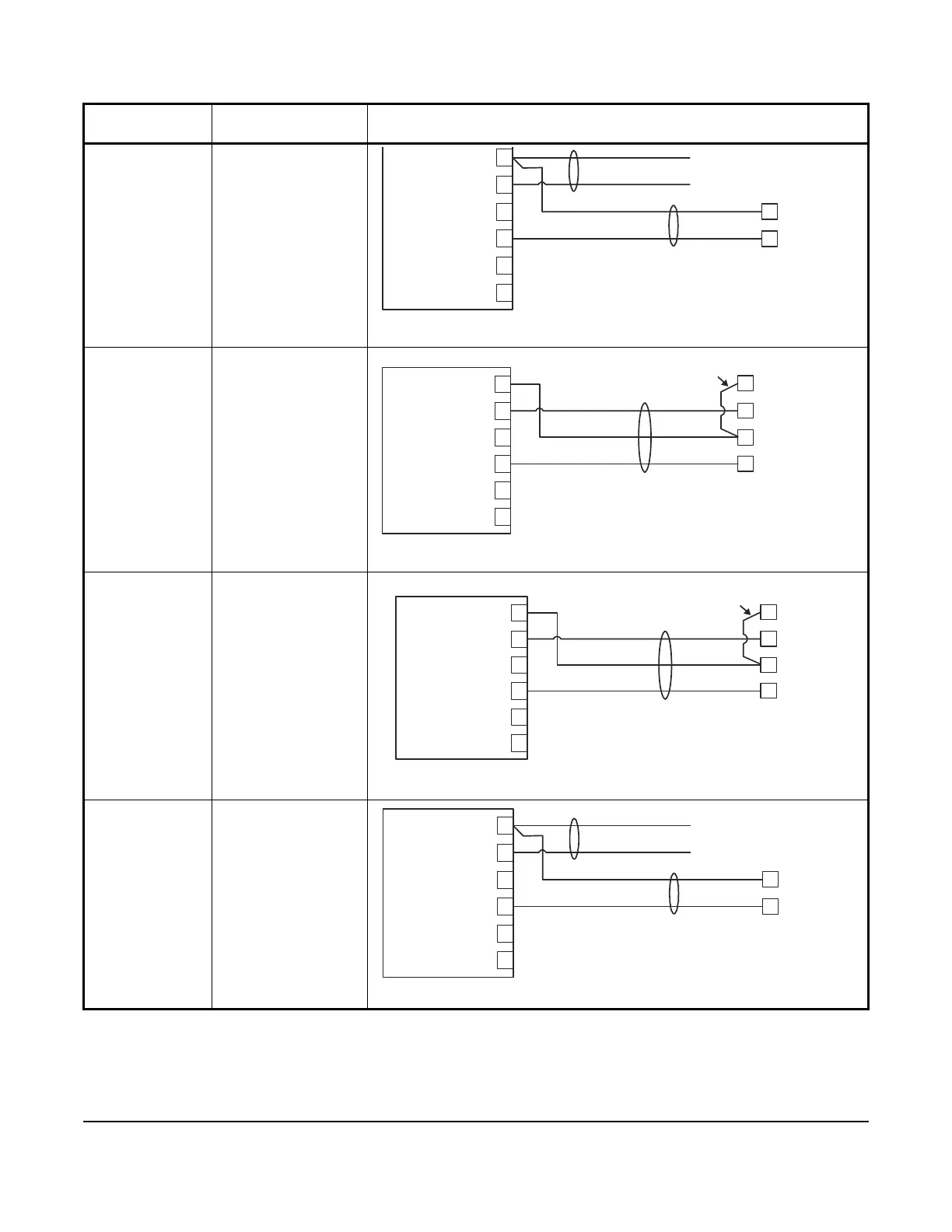
0-10 VDC Output
to Actuator
(External
Source)
CO
0–10 VDC
Output to
Actuator
(Internal Source)
CO
0–20 mA Output
to Actuator
CO
0–20 mA Output
to Actuator
CO
Table 2: Termination Details (Part 3 of 5)
Type of Field
Device
Type of Input/Output Termination Diagrams
Common
Power
Calibration Output
Current Input
Voltage Input
Feedback
Terminal Block 1
OCOM#
Controller
24 VAC COM
24 VAC HOT
Common
Power
Calibration Output
Current Input
Voltage Input
Feedback
Terminal Block 1
OCOM#
Controller
24 VAC Com
24 VAC Hot
Add Jumper from 24 VAC COM to
only one AO COM per Transformer
Common
Power
Calibration Output
Current Input
Voltage Input
Feedback
Terminal Block 1
OCOM#
Controller
24 VAC Com
24 VAC Hot
Add Jumper from 24 VAC COM to
only one AO COM per Transformer
Common
Power
Calibration Output
Current Input
Voltage Input
Feedback
Terminal Block 1
OCOM#
Controller
24 VAC COM
24 VAC HOT
 Loading...