PEAK® OEM 18 240 Volt SMART Equipment Controller Installation Instructions
7
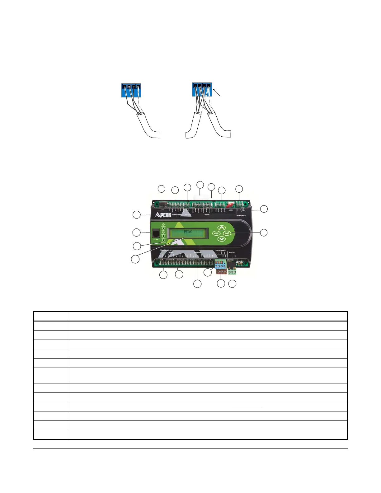
Figure 6: FC Bus Terminal Block Wiring
Figure 7: PK-OEM18x1-0 Physical Features
Table 1: OEM18x1-0 Physical Features (Part 1 of 2)
Callout Physical Feature: Description and Reference
1 120/240 VAC, Class 1 Power supply terminal block. See the Supply Power Terminal Block section.
2 24 VAC Utility Output Power for Actuator Supply
3 Two Binary Outputs: 0.5 Amp Triac (24 or 240 VAC, externally powered). See Table 3.
4 Four Binary Outputs: Relays SPST 6 (3A) (240 VAC), dry contact. Rated up to 240 VAC.
5 Mounting clips (three).
6 Three Configurable Outputs (CO) terminal blocks. Voltage Analog Output 0 to 10 VDC, 10 mA. Binary Triac
Outputs: 24 VAC, Externally Sourced. See Table 3.
7 USB Host Port
8 Cover Lift Tabs
9 Sensor Actuator (SA) Bus Port (RJ-12 6-pin Modular Jack). See SA Bus
Port section.
10 LED Status Indicators. See Table 7.
11 Four Keypad buttons
12 Display with backlight
Stranded 3-Wire Twisted Shielded Cable
Isolated Shield
Connection
Terminal
+
_
COM
SHD
To Next
Device on
the FC Bus
Segment
FC Bus
Terminal
Block Plugs
FIG: fc_bus_term
s
+
_
COM
SHD
Terminating Device
on FC Bus Segment
To Next
Device on
the FC Bus
Segment
Daisy Chained Device
on FC Bus Segment
11