System 450™ Series Modular Control Systems with Standard Control Modules Technical Bulletin8
See Table 11 on page 62 for a list of System 450 modules that can be used in
standard and hybrid analog output control systems. Refer to the System 450 Series
Modular Controls Product Bulletin (LIT-12011458) for a complete list and
description of the System 450 modules, compatible sensors and transducers, and
accessories.
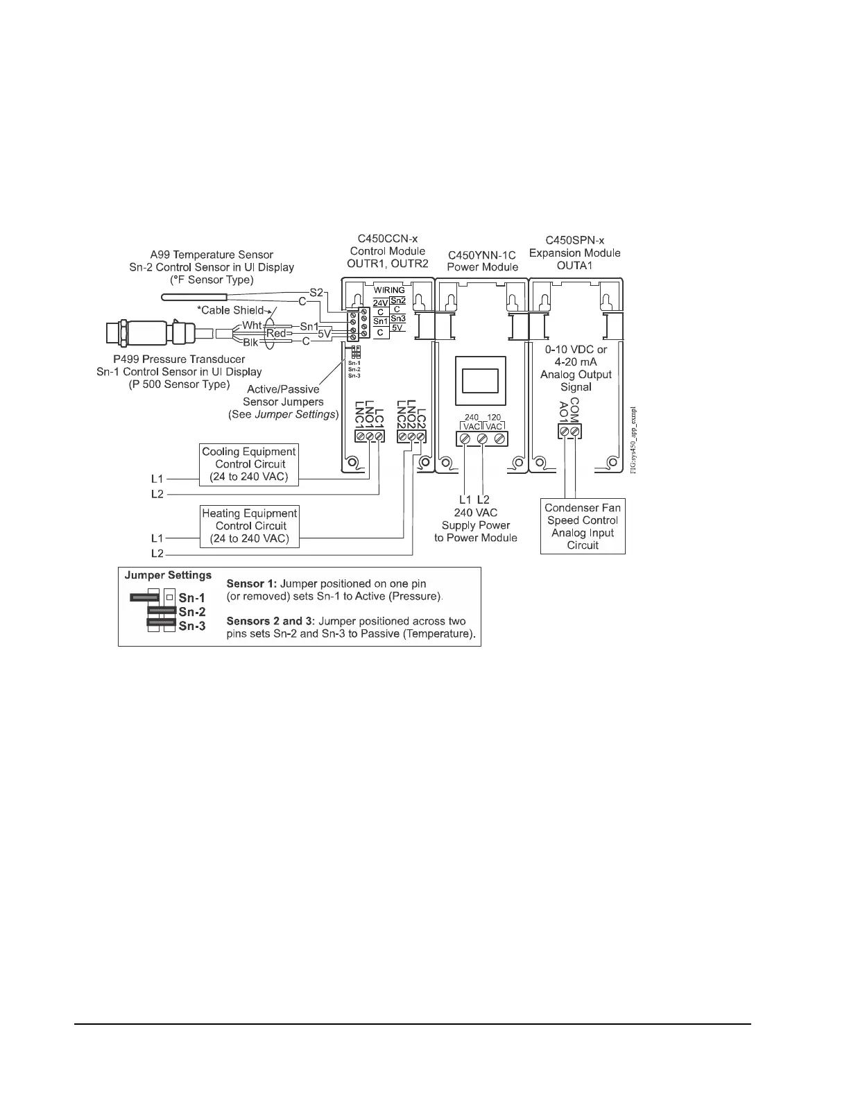
Figure 1 shows an example System 450 standard control system connected as a
room heating and cooling control system with condenser fan speed control.
Figure 3 on page 12 shows the System 450 UI Main Screens, System Status
screens, and System Setup Screens for the heating and cooling control system
shown in Figure 1.
Figure 1: System 450 Standard Control System Connected
as a Room Heating and Cooling Control System with
Condenser Fan Speed Control
* Connect cable shields
at only one point to any
“C” terminal on the
Input Terminal Block.

 Loading...


