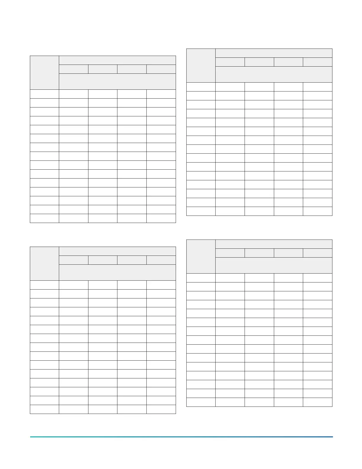
Table 25: 3.5 ton cooling charging chart for
XA(F,H)*60G and JH(E,V)T*48G in downflow and
horizontal right
Indoor wet bulb (°F) at 80°F dry bulb
57 62 67 72
Outdoor
ambient
DB (°F)
Pressure (psig) and subcooling
(°F) at liquid base valve
55 201 (4) 204 (4) 206 (4) 210 (4)
60 219 (4) 221 (4) 223 (4) 227 (4)
65 236 (4) 239 (4) 241 (4) 244 (4)
70 255 (4) 258 (4) 261 (4) 265 (4)
75 275 (4) 278 (4) 281 (4) 285 (4)
80 297 (4) 300 (5) 303 (5) 307 (5)
85 320 (5) 322 (5) 326 (5) 330 (5)
90 345 (5) 347 (5) 351 (5) 354 (5)
95 370 (5) 372 (6) 376 (5) 379 (5)
100 397 (5) 400 (6) 403 (5) 407 (5)
105 425 (5) 427 (6) 431 (5) 434 (5)
110 455 (5) 457 (6) 461 (5) 464 (5)
115 485 (5) 487 (5) 491 (5) 494 (5)
120 518 (5) 519 (5) 523 (5) 526 (5)
125 551 (5) 552 (6) 556 (5) 558 (5)
Table 26: 4 ton cooling charging chart for XAF*60G and
JH(E,V)T*48G in upflow
Indoor wet bulb (°F) at 80°F dry bulb
57 62 67 72
Outdoor
ambient
DB (°F)
Pressure (psig) and subcooling
(°F) at liquid base valve
55 218 (10) 221 (11) 224 (11) 229 (11)
60 235 (10) 238 (11) 242 (11) 246 (11)
65 253 (10) 256 (10) 259 (10) 264 (11)
70 274 (10) 277 (11) 280 (11) 284 (11)
75 295 (10) 297 (11) 300 (11) 304 (11)
80 318 (11) 320 (11) 323 (11) 327 (11)
85 341 (11) 344 (12) 346 (12) 350 (12)
90 368 (12) 369 (12) 372 (12) 376 (12)
95 394 (12) 395 (13) 398 (12) 402 (12)
100 423 (12) 424 (13) 427 (12) 430 (12)
105 452 (12) 453 (13) 456 (12) 459 (12)
110 484 (12) 484 (12) 487 (12) 491 (11)
115 516 (11) 516 (12) 519 (12) 522 (11)
120 550 (11) 550 (12) 553 (12) 557 (11)
125 585 (11) 585 (12) 588 (12) 591 (11)
Table 27: 4 ton cooling charging chart for XAH*60G and
JH(E,V)T*48G in horizontal left
Indoor wet bulb (°F) at 80°F dry bulb
57 62 67 72
Outdoor
ambient
DB (°F)
Pressure (psig) and subcooling
(°F) at liquid base valve
55 213 (9) 216 (9) 220 (9) 224 (10)
60 231 (9) 234 (9) 237 (9) 241 (10)
65 248 (8) 251 (9) 254 (9) 258 (9)
70 268 (9) 271 (9) 274 (9) 278 (9)
75 288 (9) 291 (9) 294 (9) 298 (9)
80 311 (9) 314 (10) 317 (10) 320 (10)
85 334 (10) 336 (10) 339 (10) 343 (10)
90 360 (10) 362 (11) 365 (10) 368 (10)
95 386 (10) 387 (11) 390 (11) 393 (10)
100 414 (10) 415 (11) 418 (11) 422 (10)
105 443 (10) 444 (11) 446 (11) 450 (10)
110 474 (10) 474 (11) 477 (10) 480 (10)
115 505 (10) 505 (10) 508 (10) 511 (9)
120 539 (10) 539 (10) 542 (10) 545 (9)
125 573 (10) 572 (10) 575 (10) 579 (9)
Table 28: 4 ton cooling charging chart for XA(F,H)*60G
and JH(E,V)T*48G in downflow and horizontal right
Indoor wet bulb (°F) at 80°F dry bulb
57 62 67 72
Outdoor
ambient
DB (°F)
Pressure (psig) and subcooling
(°F) at liquid base valve
55 206 (5) 209 (5) 212 (5) 217 (5)
60 223 (4) 226 (5) 229 (5) 233 (5)
65 240 (4) 243 (5) 246 (5) 249 (5)
70 259 (4) 262 (5) 265 (5) 269 (5)
75 279 (5) 281 (5) 284 (5) 288 (5)
80 301 (5) 303 (5) 306 (5) 310 (5)
85 323 (5) 325 (5) 328 (5) 331 (5)
90 348 (5) 350 (5) 353 (5) 356 (5)
95 373 (5) 374 (6) 377 (5) 380 (5)
100 400 (5) 402 (6) 404 (5) 408 (5)
105 428 (5) 429 (6) 432 (5) 435 (5)
110 458 (5) 459 (5) 461 (5) 465 (5)
115 488 (5) 489 (5) 491 (5) 494 (5)
120 521 (5) 521 (5) 524 (5) 527 (5)
125 554 (5) 553 (5) 556 (5) 559 (5)
Installation Manual: R-410A Outdoor Split-System Heat Pump - YH2F, THF2, RHP150 Series 21
Johnson Controls Ducted Systems

 Loading...


