EasyManuals Logo
Home>Johnson Controls>Controller>S321-IP

Johnson Controls S321-IP User Manual

Johnson Controls S321-IP
27 pages
To Next Page IconTo Next Page
To Previous Page IconTo Previous Page
Page #23 background imageLoading...
Page #23 background image
S321-IP Network Controller Hardware Installation
24-10239-480 Rev. F
19
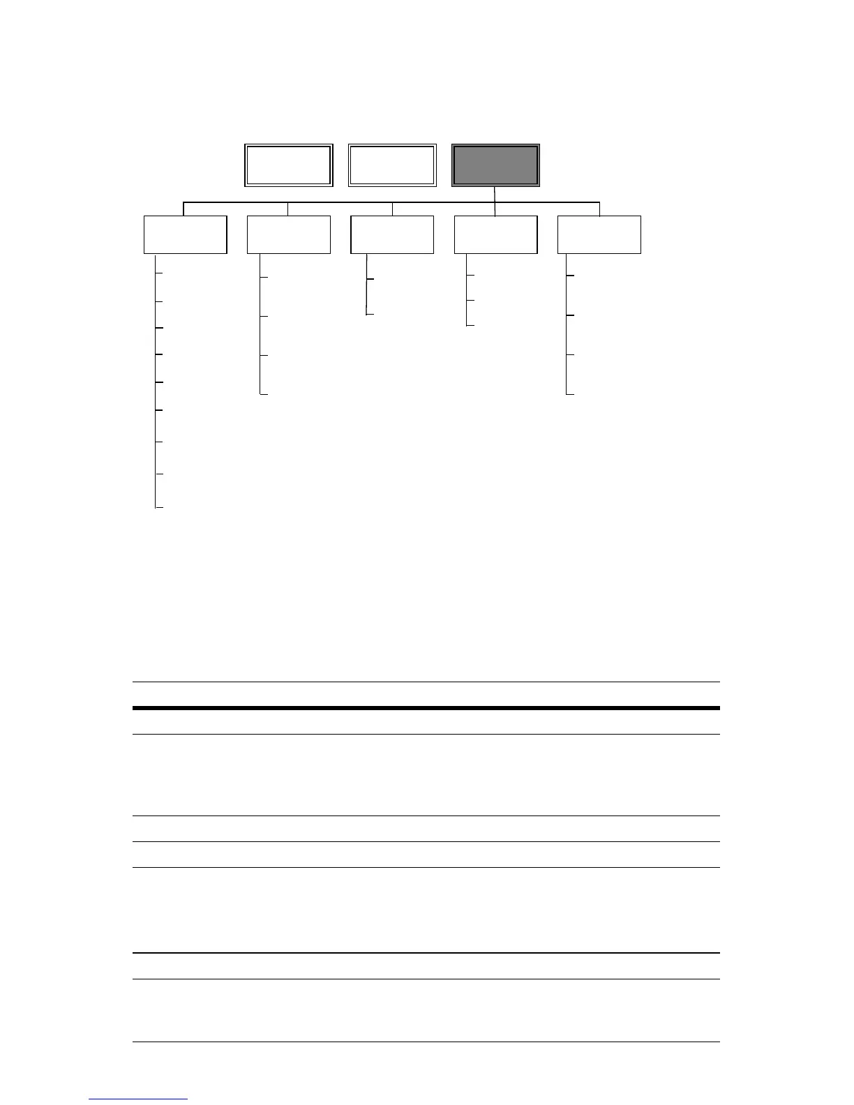
See the diagram below for the Network menu navigation map:
T
ECHNICAL SPECIFICATIONS
The terminal is expected to operate at moderate temperature variation, non-
condensing humidity variation, moderate vibration, and possible dust
contamination.
Item Specification
Input Power +12 to +24 VDC or 16 to 24 VAC at 24W
Reader Interface 2-wire Wiegand (up to 256 bits)
12 VDC, 250 mA (typical), 500 mA (peak)
Red indicator
Green indicator
General Purpose Inputs Resistive load
Relay Outputs 1 A max. 0-24 VDC/VAC, 25 VA max
Red LED/Green LED
Outputs
50 mA max. 0-24 VDC.
These open collector outputs can be damaged by alternating
current (AC) potentials as low as 1 VAC. Connect the LED
outputs only to direct current (DC) loads up to 24VDC.
Communications 10/100 Base-T Ethernet using TCP/IP protocol
Certifications FCC, Class B
•CE Mark
•C-Tick
SNMP Agent
Enable
System
Information
Community
Traps
Configuration
FTP Enable
Certificate
Private Key
Self-Signed
Certificate
IP
SNMP FTP SSL HTTP
Main Database Network
Username
and Password
Timeout
Maximum Bytes
Allowed
Admin Account
User Account
DHCP Enable
IP Address
Network Mask
Gateway
MAC Address
P2000 Host
Name
User Name
or IP
Name
P2000 Host
IP Address

Questions and Answers:

Question and Answer IconNeed help?

Do you have a question about the Johnson Controls S321-IP and is the answer not in the manual?

Johnson Controls S321-IP Specifications

General IconGeneral
BrandJohnson Controls
ModelS321-IP
CategoryController
LanguageEnglish

Related product manuals