RWF II ROTARY SCREW COMPRESSOR UNITS
INSTALLATION
070.610-IOM (JUN 11)
Page 12
• Remote – The external controller would reinitialize the
panel and proceed to run as required.
• Manual – The compressor will have to be restarted
manually after the 3phase bus fault has been cleared.
If the local power distribution system is unstable or prone
to problems, there are other recommendations to satisfy
these problems. If power spikes or low or high line voltages
are the problem, then we recommend the use of a Sola®
constant voltage (CV) transformer with a line suppression
feature. If a phase loss occurs, then you will typically get a
high motor amp shutdown. If problems continue to exist, then
an examination of the plant’s power factor may be in order.
Unless careful design failure analysis is considered in the
implementation of power systems, the alternative solutions
provide a safer and less expensive implementation. In either
case, only one Sola
®
may be used per compressor. Each
compressor needs to be individually isolated from each other
through a dedicated control transformer. Sharing a common
control power source is an invitation for ground loops and
the subsequent unexplainable problems.
MOTOR STARTER PACKAGE
Motor starter and interlock wiring require ments are shown
in the Starter Wiring Diagram. All of the equipment shown
is supplied by the installer unless a starter package is pur
chased separately from Johnson ControlsFrick
®
. Starter
packages should consist of:
1. The compressor motor starter of the specied HP and
voltage for the starting method specied (acrosstheline,
wyedelta, or solidstate).
NOTE: If starting methods other than across-the-line are
desired, a motor/compressor torque analysis must be
done to ensure that sufcient starting torque is avail-
able, particularly in booster applica tions. Contact Johnson
Controls-Frick
®
if assistance is required.
2. If specied, the starter package can be supplied as a
combination starter with circuit breaker disconnect. Howev er,
the motor overcurrent protection/disconnection device can
be applied by others, usually as a part of an electrical power
distribution board.
3. The oil pump starter with fuses, or in the case where the
compressor motor is a different voltage from the oil pump
motor, with a circuit breaker disconnect suitable for sepa rate
power feed.
4. A 3.0 KVA control power transformer (CPT) to supply
120 volt control power to the microprocessor control sys
tem and separator oil heaters is included. If environ mental
condi tions require more than the usual two 500 watt oil
heaters, an appropriately oversized control transformer will
be required. If frequent power uc tuations are anticipat ed or
extremely noisy power lines are encoun tered, a regulating
control transformer should be considered. Contact Johnson
ControlsFrick
®
for assistance.
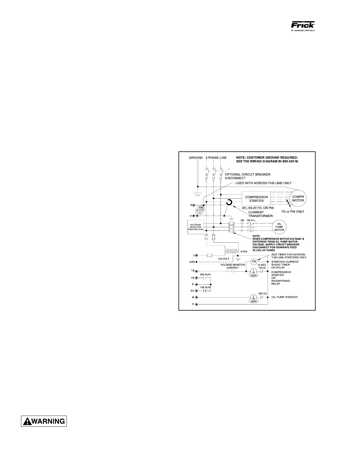
5. For customersupplied acrosstheline starters, a shunt
ing device must be installed across the Current Transformer
(terminals 3 & 4).
If the shunting device is not installed,
the Analog I/O board on the
Quantum
™
LX panel may be severely
damaged at start-up. See Figure 12.
6. One each normally open compressor motor and oil pump
motor starter auxiliary contact should be supplied. In addition
to the compressor and oil pump motor starter coils, the CT
and CPT secondaries should be wired as shown on the starter
package wiring diagram. The load on the control panel for
the compressor motor starter coil should not exceed a 2 amp
load. For larger starters, an interposing relay must be used
to switch the compres sor motor starter coil(s).
NOTE: Do not install a compressor HAND/OFF/AUTO
switch in the starter package as this would bypass the
compressor safety devices.
7. The compressor motor Current Transformer (CT) is in
stalled on any one phase of the compressor leads.
NOTE: The CT must see all the current of any one phase,
therefore in wye-delta applications BOTH leads of any
one phase must pass through the CT.
Figure 12 - Starter Wiring Diagram