RWF II ROTARY SCREW COMPRESSOR UNITS
OPERATION
070.610-IOM (JUN 11)
Page 14
Operation
OPERATION and START-UP INSTRUCTIONS
The Frick
®
RWF II Rotary Screw Compressor Unit is an inte
grated system consisting of seven major subsystems:
1. Quantum
™
LX Control Panel
(See publications 090020 O, M, & CS)
2. Compressor
3. Compressor Lubrication System
4. Compressor Oil Separation System
5. Compressor Hydraulic System
6. Compressor Oil Cooling System
7. Compressor EasyStart System
The information in this section of the manual provides the
logical stepbystep instructions to properly start up and
operate the RWF II Rotary Screw Compressor Unit.
THE FOLLOWING SUBSECTIONS MUST BE READ AND
UNDERSTOOD BEFORE ATTEMPTING TO START OR OP-
ERATE THE UNIT.
SGC COMPRESSOR
The Frick
®
RWF II rotary screw compressor utilizes mating
asymmetrical prole helical rotors to provide a continuous
ow of refriger ant vapor and is designed for both high
pressure and lowpressure applica tions. The compressor
incorpor ates the following features:
1. Highcapacity roller bearings to carry radial loads at both
the inlet and outlet ends of the compres sor.
2. Heavyduty, fourpoint angularcontact ball bearings to
carry axial loads are mounted at the discharge end of com
pressor.
3. Balance pistons located in the inlet end of the compres sor
to reduce axial loads on the axial load bearings and increase
bearing life.
4. Movable slide valve to provide fully modulating capacity
control from 100% to approximately 10% of full load capacity.
5. Volume ratio control to allow innite ly variable volume
ratio from 2.2 to 5.0 during compres sor operation for all
models.
6. A hydraulic unloader cylinder to operate the slide stop
and slide valve.
7. Bearing and casing design for 400 PSI discharge pres
sure. This PSI rating applies only to the compressor and
does not reect the design pressure of the various system
components.
8. All bearing and control oil vented to closed thread in the
compressor instead of suction port to avoid performance
penalties from superheating suction gas.
9. Shaft seal design to maintain operating pressure on seal
well below discharge pressure, for increased seal life.
10. Oil injected into the rotors to maintain good volumetric
and adiabatic efciency even at very high compression ratios.
11. Shaft rotation clockwise facing compressor, suitable for
all types of drives. SEE FOLLOWING WARNING.
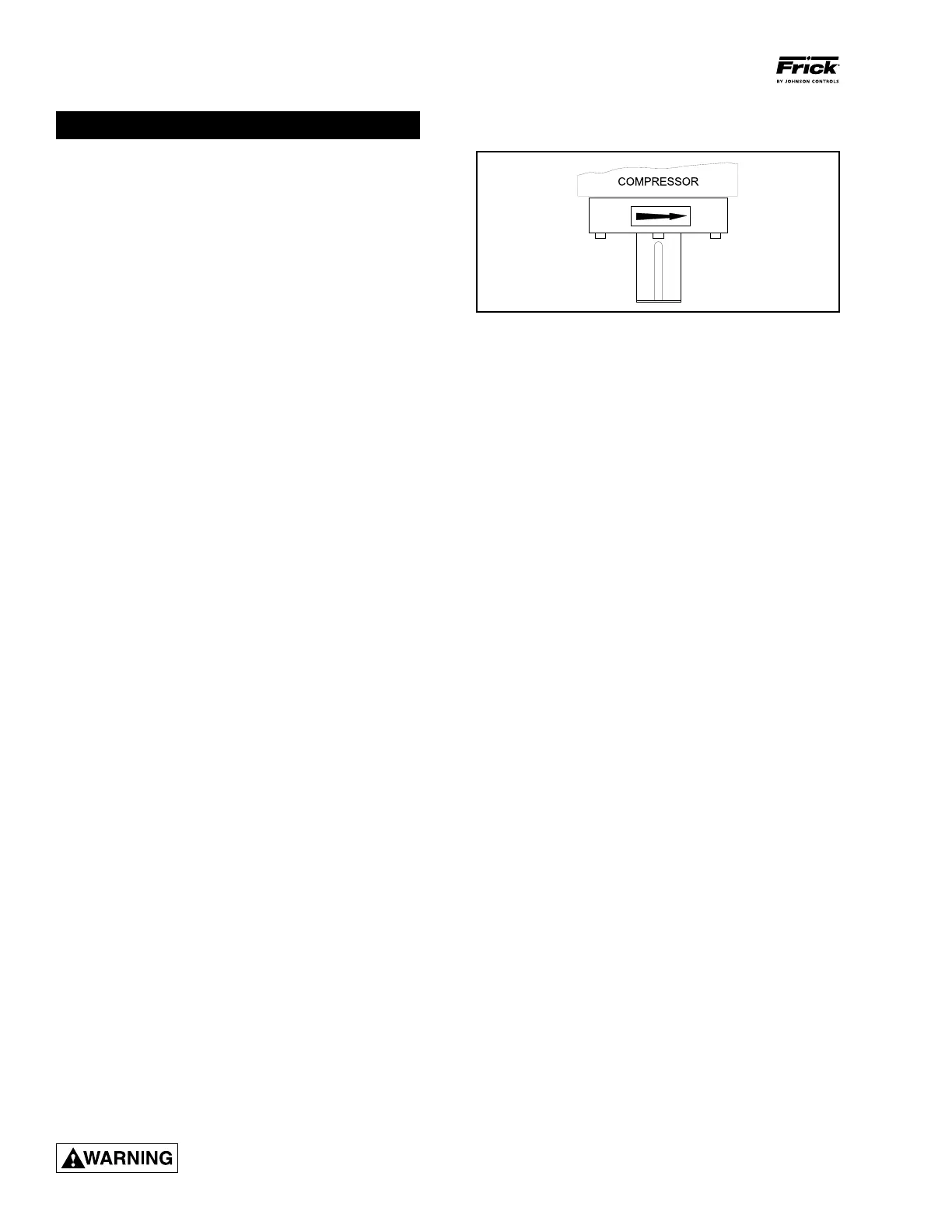
Compressor rotation is clockwise
when facing the compressor drive
shaft. See Figure 15. The compressor should never be
operated in reverse rotation as bearing damage will result.
Figure 15 - Shaft Rotation Direction
12. Dual compressor casing design for very low airborne noise
transmission.
13. Suction ange is 300 psig ANSI type.
14. Integral suction strainer is provided on models 100 – 480
and 546. Models 496 – 1080 have external strainer.
15. "D" Flange adapter for bolting directly to motor.
COMPRESSOR LUBRICATION SYSTEM
The lubrication system on an RWF II screw com pres sor unit
performs several functions:
1. Provides lubrication to bearings and seal.
2. Provides a cushion between the rotors to minimize noise
and vibrations.
3. Helps keep the compressor cool and prevents overheat ing.
4. Provides an oil supply to hydraulically actuate the slide
valve and slide stop.
5. Provides oil pressure to the balance pistons to help in
crease bearing life.
6. Provides an oil seal between the rotors to prevent rotor
contact or gas bypassing.
The compressor unit may be equipped with either a no
pump or a demand pump lubrication system. Additionally,
either system may contain dual oil lters and liquid injection,
watercooled, or thermosyphon oil cooler for compressor
oil cooling.
NO PUMP OIL SYSTEM
The RWF II screw compressor unit is designed to be selflu
bricating. Oil being supplied to the compres sor from the oil
separator is at system head pressure. Within the compressor,
oil porting to all parts of the compressor is vented back to
a point in the compres sor’s body that is at a pressure lower
than compressor discharge pressure. The compressor’s nor
mal operation makes the compressor unit operate essentially
as its own oil pump. All oil entering the compressor is moved
by the compressor rotors out the compressor outlet and back
to the oil separator.
For normal highstage operation, an oil pump is not required.