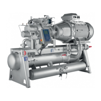
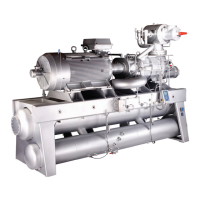
RWF II ROTARY SCREW COMPRESSOR UNITS
MAINTENANCE
070.610-IOM (JUN 11)
Page 35
PRESSURE TRANSDUCERS - TESTING
1. Shut down the compressor and allow pressures to equalize.
2. Isolate suction transducer PE4 from the unit and depres
surize. Ensure that the transducer has proper voltage for
excitation. Measure across the red and black wires (power
and DC common) of the transducer. Voltage should be 11.8
to 15 VDC. NOTE: Recover or transfer all refrigerant vapor,
in accordance with local ordinances, before opening to
atmosphere.
3. Measure the voltage of PE4 on connector P6A (terminals
WHT and BLK) on the Analog Board with a digital voltmeter.
4. The voltage reading should be 1.48 VDC to 1.72 VDC at
standard atmospheric pressure (14.7 PSIA or 0 PSIG). When
checking transducers at higher elevations, an allowance in
the readings must be made by subtracting approximately 0.02
VDC per 1000 feet of elevation above sea level. Therefore,
if PE4 is measured at 5000 feet elevation under relatively
normal weather conditions, the output voltage should differ
by 0.10 VDC to read between 1.38 VDC and 1.62 VDC.
5. Isolate the oil pressure transducer PE1 from the package
and open it to atmosphere.
6. Measure the voltage of PE1 on connector P5A (terminals
WHT and BLK) on the Analog Board.
7. The voltage reading should be between 1.1 VDC and 1.29
VDC at standard atmospheric pressure. PE1, PE2, and PE3
all have a span of 500 PSI as compared to PE4 with a span
of 200 PSI. Therefore, atmospheric pressure changes have a
lesser effect which is 0.0067 VDC per 1000 feet of elevation
and 0.00067 VDC per 0.1 inch Hg barometric deviation.
8. Isolate transducer PE2 from the package and depres
surize. NOTE: Recover or transfer all refrigerant vapor,
in accordance with local ordinances, before opening to
atmosphere.
9. Measure the voltage of PE2 on connector P5B (terminals
WHT and BLK) on the Analog Board.
10. The voltage reading should be between 1.1 VDC and 1.29
VDC at standard atmospheric pressure (see Step 12).
11. Since the discharge pressure, PE3, cannot be closed off
from its sensing point (code require ments), close all trans
ducers from atmosphere and open them to their sensing
points so all transducers can equalize to separator pressure.
12. Measure the voltage of PE3 on connector P5B (terminals
WHT and BLK) on the Analog Board.
13. Measure the voltage of PE1 on connector P5A (terminals
WHT and BLK) on the Analog Board.
14. These two voltages should be within .04 VDC of one
another.
15. Test is complete.
PRESSURE TRANSDUCERS - REPLACEMENT
1. Shut off control power.
2. Close the applicable transducer isolation valve. NOTE: To
change the discharge pressure transducer (PE-3), it will be
necessary to depressurize the entire compressor package.
Follow "General Instructions For Replacing Compressor
Unit Components" before going to step 3.
3. Refer to the WIRING HARNESS section, External Transduc
ers for Board #1, to identify the wiring harness connectors.
4. Loosen screw and disconnect wiring harness connector
from transducer.
5. Unscrew the transducer using a wrench on the metal hex
at the base of the transducer. DO NOT ATTEMPT TO LOOSEN
OR TIGHTEN TRANSDUCERS BY THEIR TOP CASING.
6. Install new transducer.
7. Reconnect the wiring harness to the transducer.
8. Reopen the transducer isolation valve.
9. Turn on control power.
NOTE: The Pressure Transducer is factory set. If calibra-
tion is required, refer to Amalog Calibration Instruction
in publication 090-020 M.
PRESSURE TRANSDUCER CONVERSION DATA
200 psi 500 psi
Sensor Range - PSIG* Range - PSIG*
Voltage low high low high
1.0 29.92" 9.57" 29.92" 4.1
1.1 29.92" 0.3 29.92" 16.6
1.2 29.92" 5.3 17.10" 29.1
1.3 19.74" 10.3 4.1 41.6
1.4 9.57" 15.3 16.6 54.1
1.5 0.3 20.3 29.1 66.6
1.6 5.3 25.3 41.6 79.1
1.7 10.3 30.3 54.1 91.6
1.8 15.3 35.3 66.6 104.1
1.9 20.3 40.3 79.1 116.6
2.0 25.3 45.3 91.6 129.1
2.1 30.3 50.3 104.1 141.6
2.2 35.3 55.3 116.6 154.1
2.3 40.3 60.3 129.1 166.6
2.4 45.3 65.3 141.6 179.1
2.5 50.3 70.3 154.1 191.6
2.6 55.3 75.3 166.6 204.1
2.7 60.3 80.3 179.1 216.6
2.8 65.3 85.3 191.6 229.1
2.9 70.3 90.3 204.1 241.6
3.0 75.3 95.3 216.6 254.1
3.1 80.3 100.3 229.1 266.6
3.2 85.3 105.3 241.6 279.1
3.3 90.3 110.3 254.1 291.6
3.4 95.3 115.3 266.6 304.1
3.5 100.3 120.3 279.1 316.6
3.6 105.3 125.3 291.6 329.1
3.7 110.3 130.3 304.1 341.6
3.8 115.3 135.3 316.6 354.1
3.9 120.3 140.3 329.1 366.6
4.0 125.3 145.3 341.6 379.1
4.1 130.3 150.3 354.1 391.6
4.2 135.3 155.3 366.6 404.1
4.3 140.3 160.3 379.1 416.6
4.4 145.3 165.3 391.6 429.1
4.5 150.3 170.3 404.1 441.6
4.6 155.3 175.3 416.6 454.1
4.7 160.3 180.3 429.1 466.6
4.8 165.3 185.3 441.6 479.1
4.9 170.3 190.3 454.1 491.6
5.0 175.3 195.3 466.6 504.1
At 0 psig 1.094 V 1.494 V 0.968 V 1.268 V
* Below 0 PSIG measured in inches of mercury.

 Loading...


