RWF II ROTARY SCREW COMPRESSOR UNITS
INSTALLATION
070.610-IOM (JUN 11)
Page 9
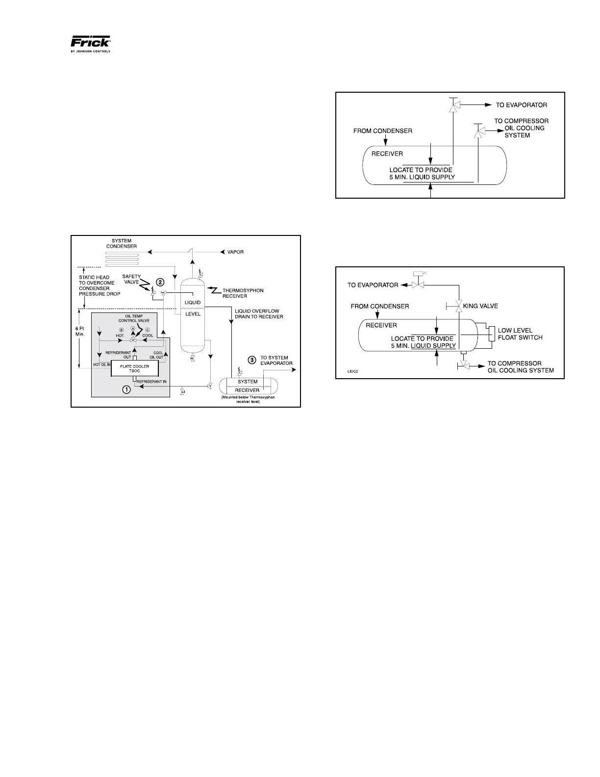
ator tube to ensure continued oil cooling when the receiver
level is low.
Figure 6 - Dual Dip Tube
The level-control method (Figure 7) utilizes a float level
control on the receiver to close a solenoid valve feeding the
evaporator when the liquid falls below that amount necessary
for 5 minutes of liquid injection oil cooling.
Figure 7 - Level Control
LIQUID LINE SIZES/RECEIVER VOLUME
Liquid line sizes and the additional receiver volume (quanti-
ty of refrigerant required for 5 minutes of liquid injection oil
cooling) are given in TABLE 1.
WATER-COOLED OIL COOLING (OPTION AL)
The plateandshell type watercooled oil cooler is mounted
on the unit complete with all oil piping. The customer must
supply adequate water connections. Determine the size of
the watercooled oil cooler supplied with the unit, as outlined
on the Frick P&I diagram and arrangement drawings. The
water supply must be sufcient to meet the required ow.
A closedloop system is recommended for the waterside of
the oil cooler. Careful attention to water treatment is es
sential to ensure adequate life of the cooler if cooling tower
water is used. It is imperative that the condition of cooling
water and closed-loop uids be analyzed regularly and
as necessary and maintained at a pH of 7.4, but not less
than 6.0 for proper heat exchanger life. After initial start
up of the compressor package, the strainer at the inlet of
the oil cooler should be cleaned several times in the rst 24
hours of operation.
In some applications, the plate and shell oil cooler may be
subjected to severe water conditions, including high tem
perature and/or hard water conditions. This causes acceler
ated scaling rates which will penalize the performance of the
heat exchanger. A chemical cleaning process will extend the
life of the Plate and Shell heat exchanger. It is important to
establish regular cleaning schedules.
Cleaning: A 3% solution of Phosphoric or Oxalic Acid is rec
ommended. Other cleaning solutions can be obtained from
outside of the shaded area on the piping diagram with con
sideration given to the following:
1. The refrigerant source, thermosyphon or system receiv er,
should be in close proximity to the unit to minimize piping
pressure drop.
2. The liquid level in the refrigerant source must be 6 to 8
feet minimum above the center of the oil cooler.
3. A safety valve should be installed if refrigerant isolation
valves are used for the oil cooler.
NOTE: The component and piping arrangement shown in
Figure 5 is intended only to illustrate the operating principles
of thermosyphon oil cooling. Other component layouts may
be better suited to a specic installation. Refer to publica-
tion 070-900E for additional information on Thermosyphon
Oil Cooling.
Figure 5 - TSOC Piping Arrangement
1. The thermosyphon oil cooler is supplied with oil side
piped to the compressor unit and stub ends supplied on the
refrigerant side.
2. A refrigerantside safety valve is required in this location
only when refrigerant isolation valves are installed between
the cooler and thermosyphon receiver. If no valves are used
between the cooler and TSOC receiver, the safety valve on
the TSOC receiver must be sized to handle the volume of
both vessels. Then, the safety valve on the cooler vent (liquid
refrigerant side) can be eliminated.
3. The system receiver must be below the thermosyphon
receiver in this arrangement.
LIQUID INJECTION OIL COOLING (Optional)
The liquid injection system provided on the unit is self
contained but requires the connection of the liquid line sized
as shown in Table 1.
It is IMPERATIVE that an uninterrupted supply of high pres
sure liquid refrigerant be provided to the injection system
at all times. Two items of EXTREME IMPOR TANCE are the
design of the receiver/liquid injection supply and the size of
the liquid line.
It is recommended that the receiver be oversized sufcient ly
to retain a 5minute supply of refrig erant for oil cooling. The
evaporator supply must be secondary to this consideration.
Two methods of accomplishing this are shown.
The dual dip tube method (Figure 6) uses two dip tubes in
the receiver. The liquid injection tube is below the evapor