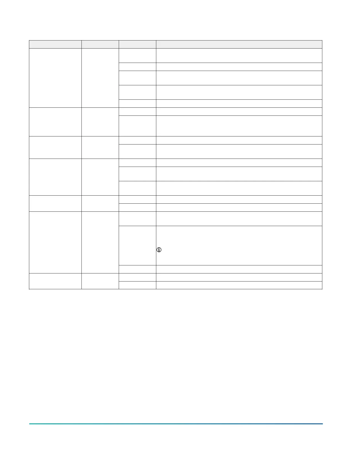
Table 10: SNC LED designations, normal statuses, descriptions, and other conditions
LED name Color State Description
Flashing blue
and purple
1 blink per second (1 Hz) = Normal operating system and all monitored
processes start and the device is running
On blue Power is supplied by 24 VAC, but controller is non-operational
Medium flicker,
purple and blue
2 blinks per second (2 Hz) = SNC starting up
Fast flicker,
purple and blue
5 blinks per second (5 Hz) = SNC shutting down
HEARTBEAT Multi-color: blue
or purple
Off No power
Off No faults and normal operationFAULT Red
On Device fault or no application loaded. Diagnostics are running or fault
conditions are detected. For example, excessive memory or flash usage, or a
high CPU/PWB temperature.
Flashing 1 blink per second (1 Hz) = indicates communication activitySA BUS Green
On Devices have been defined but none are communicating (supervisory
controller transmitting only)
Flashing 1 blink per second (1 Hz) = indicates communication activity
Off No devices are communicating or no controllers have been configured to
work with this bus
FC BUS Green
On Controllers have been defined but none are communicating (supervisory
controller transmitting only)
Flickering Data is transferring on the Ethernet connectionETH-1 and ETH-2 Green
Off No communications
Flashing Flash green = 1 blink per second (1 Hz), an approved device or devices are
connected and communicating correctly to either USB-1|2
On Solid red = an unapproved device is connected to USB 1 and/or USB 2. In this
case a user needs to sequentially remove each device until the LED flashes
green or the LED is turned off.
Note: Only approved USB adapters that have been tested and
qualified function with the SNC. Non-qualified adapters do not
function with the SNC.
USB-1|2 Green or Red
Off No USB device is connected
On On Steady = end-of-line termination is enabled for the Field Bus connectionEOL Yellow
Off Off Steady = indicates the end of line termination network is disabled
F4-SNC Installation Guide 19