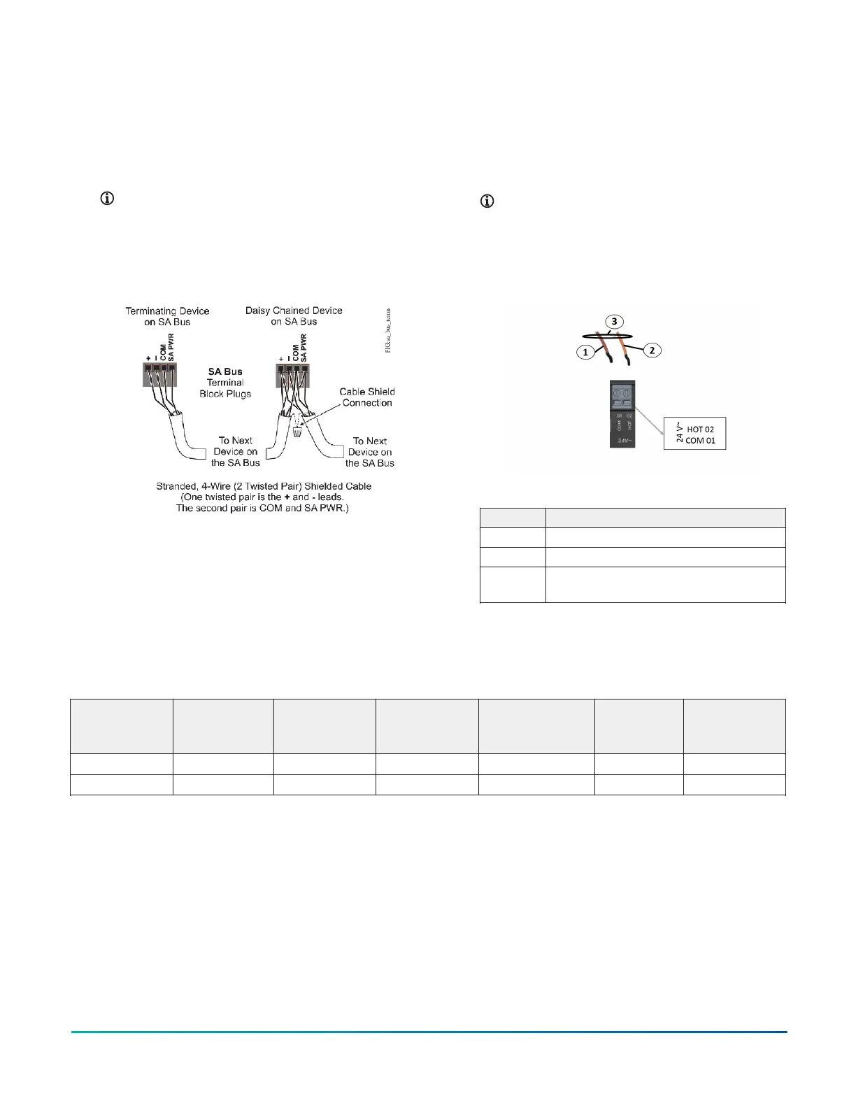
and cables for more information. The SA Bus port pin
assignment is shown in Figure 4 and Table 2.
Connecting to the SA Bus terminal
1. Connect the 4-wire bus cable to the removable
orange 4-pin terminal block Sensor/Actuator (SA)
Bus, labeled SA BUS.
Note: Only connect terminal devices to either
the SA Bus port or to the SA Bus 4-pin terminal
block, not both.
Figure 6: SA Bus terminal block wiring
2. Go to Connecting the power source.
Connecting the power source
1. Connect power to the SNC using a 24 VAC power
transformer, connect the 24 VAC supply power
wires from the transformer to the gray 2-pin
terminal block labeled 24 V~ on the SNC (Figure 7
and Table 3 ). The connections are HOT and COM
(common).
Note: Power supply wire colors may be
different on transformers not manufactured
by Johnson Controls. Follow the transformer
manufacturer’s instructions and the project
installation drawings.
Figure 7: Supply power wiring (24 VAC transformer)
Table 3: Power source connection detail
Callout Description
1 Brown wire (COM)
2 Orange wire (24 VAC)
3 Wires from Johnson Controls 24 VAC, Class
Power Transformer
Connecting input and output terminals
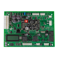
The SNC2515x-0x/x supports up to 40 hard-wired onboard I/O points, 25 inputs and 15 outputs. The SNC1612x supports
up to 28 hard-wired onboard I/O points, 16 inputs and 12 outputs.
Table 4: Onboard I/O points
SNC Total I/O Universal
Inputs (UI)
Binary Inputs
(BI)
Configurable
Outputs (CO)
Analog
Outputs
(AO)
Binary
Outputs (BO)
SNC2515x-0x/x 40 14 11 4 4 7
SNC1612x-0x/x 28 10 6 4 4 4
F4-SNC Installation Guide 7