Important: Utiliser ce SNC uniquement en tant
que dispositif de contrôle de fonctionnement.
Lorsqu'une défaillance ou un dysfonctionnement
du SNC risque de provoquer des blessures ou
d'endommager l'équipement contrôlé ou un
autre équipement, la conception du système de
contrôle doit intégrer des dispositifs de protection
supplémentaires. Veiller dans ce cas à intégrer de
façon permanente d'autres dispositifs, tels que
des systèmes de supervision ou d'alarme, ou des
dispositifs de sécurité ou de limitation, ayant une
fonction d'avertissement ou de protection en cas de
défaillance ou de dysfonctionnement du SNC.
Important:
• Do not apply power to the SNC before you
complete and check connections. Short circuits
or improperly connected wires may result in
permanent damage to the equipment.
• Use copper conductors only. Make all wiring in
accordance with local, national, and regional
regulations.
• The SNC is a low-voltage device. Do not exceed
the SNC electrical ratings. Applying high voltage
to the SNC will void any warranties and may result
in permanent damage.
• Prevent any electrostatic discharge (ESD) to the
SNC. Static electric discharge can damage the SNC
and void any warranties.
Follow these guidelines when you wire the SNC:
• Route the supply power wires and communication
cables at least 50 mm (2 in.) away from the vent slots in
the sides of the SNC housing.
• Provide slack in the wires and cables. Keep cables
routed neatly around the SNC to promote good
ventilation, LED visibility, and ease of service.
• Ensure that the building automation network wiring
meets the specifications, rules, and guidelines in Wiring
considerations and guidelines.
• Follow the transformer manufacturer’s instructions
and the project installation drawings. Power supply
wire colors may be different on transformers not
manufactured by Johnson Controls.
• Verify that transformer phasing is uniform across the
devices. Power network devices with uniform 24 VAC
supply power phasing to reduce noise, interference,
and ground loop problems.
• Do not connect the SNC to an earth ground connection.
Connecting to the FC Bus port
The FC Bus port is an RJ12, 6-position modular jack that
provides a connection for the Mobile Access Portal (MAP).
The FC Bus port is connected internally to the FC Bus
terminal block and so they share only one communication
protocol. See Communications Bus and supply terminal
blocks, functions, ratings, requirements, and cables for
more information. The FC Bus port pin assignment is
shown in Figure 4 and Table 2.
Figure 4: Pin number assignments for FC Bus port or
SA Bus port
Table 2: Pin number assignments for FC Bus port or SA
Bus port (RJ12 modular jack)
Callout Signal
1 FC Bus or SA Bus (+)
2 FC Bus or SA Bus (-)
3 Bus and Power Common
4 Power (15 VDC)
5 Bus and Power Common
6 Power (15 VDC)
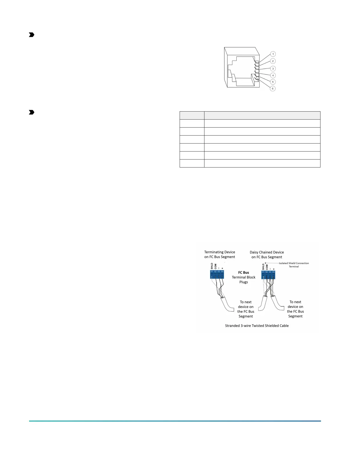
Connecting to the FC Bus terminal
About this task:
To connect devices to the FC Bus, complete the following
steps:
1. Connect the 3-wire bus cable to the removable blue
4-pin terminal block labeled FC BUS as shown in
Figure 5.
Figure 5: FC Bus terminal block and wiring connections
2. Set the FC EOL switch to the proper position. See
the note in Setting the EOL switch.
3. Go to Connecting the power source.
Connecting to the SA Bus port
The SA Bus port is an RJ12, 6-position modular jack that
provides a connection for the MAP, or other SA Bus
devices with RJ12 plugs.
The Sensor port is connected internally to the SA Bus
terminal block. See Communications Bus and supply
terminal blocks, functions, ratings, requirements,
F4-SNC Installation Guide6