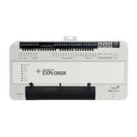
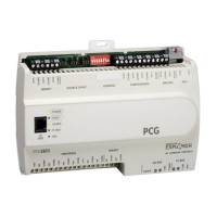
Table 1: Physical features of the SNC2515x-0x/x and
SNC1612x-0x/x
Callout Physical features
17 Reset button. See Reset button for more
information
18 Recovery button. See Recovery button for
more information.
Installation
Follow these guidelines when you transport and use the
SNC:
• Transport the SNC in the original container to minimize
vibration and shock damage to the SNC.
• Verify that all the parts shipped with the SNC are
present.
• Do not drop the SNC or subject it to physical shock.
• Do not use non-qualified USB adapters in the two
USB ports. The USB ports only function with the USB
adapters that are tested and qualified for use on the
SNC. Non-qualified adapters do not function in the USB
ports of the SNC. See Accessories ordering information
for the list of qualified and supported USB adapters.
Important: Do not open the housing for any reason.
The supervisory controller has no user-serviceable
parts inside. Tamper-evident labels on the device
caution installers, service technicians, building
owners, and our RMA inspectors from unauthorized
opening or tampering of the device.
Parts included
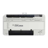
• One F4-SNC Supervisory Controller
• One F4-SNC Pack Sheet (Part No. A163816VBP)
Materials and special tools needed
You can mount the SNC by using the fasteners option or
the DIN rail option.
• Fasteners option - Three fasteners appropriate for the
mounting surface:
- #8 screws - North America
- M4 screws - Europe
• DIN rail option - 20.3 cm (8 in.) DIN rail for DIN rail
mount applications only.
Mounting
Location considerations
Follow these guidelines when you mount an SNC:
• Ensure that the mounting surface can support the SNC
and any user-supplied enclosure.
• Mount the SNC in the proper orientation (horizontal
preferred, vertical acceptable).
• Mount the SNC on an even surface in wall mount
applications whenever possible.
• Mount the SNC in areas free of corrosive vapors and
observe the environmental limitations listed in the SNC
technical specifications section.
• Do not mount the SNC on surfaces that are prone
to vibration, such as duct work, or in areas where
electromagnetic emissions from other devices or wiring
can interfere with SNC communication.
• Allow sufficient space for cable and wire runs and
terminal connections.
• Mount the power supply above the SNC to ensure
adequate heat dissipation and to position close to the
power wiring conduit.
• Do not install the SNC in an airtight enclosure. Make
sure the enclosure offers sufficient ventilation to
ensure the temperature in the enclosure does not
exceed 50°C (122°F).
• Mount the SNC so that the enclosure wall or the
transformer does not obstruct ventilation of the SNC
housing.
F4-SNC Installation Guide 3
 Loading...
