JOHNSON CONTROLS
8
FORM 130.13-NOM1 (114)
MAINTENANCE
Optional Damper Actuator
An optional factory mounted oating type actuator
is available, which mounts directly to the damper
operating shaft. The actuator is not provided with and
does not require any limit switches but is electronically
protected against overload.
Manual Override
A button on the side of the actuator cover disengages
the gear train so the drain shaft can be moved manually.
Releasing the button will re-engage the gear train.
Mechanical Angle of Rotation Stops
The adjustable stops may be field adjusted to halt
the rotation of the damper blade before the damper
blade reaches the damper stops. The actuator can be
indenitely stalled in any position without harm.
1. Loosen the two end stop screws using a No. 2
Phillips head screwdriver, being careful not to
unscrew the captive nut under the slot.
2. Move the stops (in 2.5° steps) to the desired posi-
tion and retighten the screws.
External Terminal Strip
The external terminal strip is located on the top of the
actuator. Connections are numbered. The terminals
are designed for 26 to 16 gauge wires. For most
installations, 18 or 16 gauge wire will work well with
the actuator (see table 5 for maximum wire lengths).
Overload Protection
The actuators are electronically protected against
mechanical overload. In the actuator, an electronic
circuit maintains the current at a level that will not
damage the motor while providing adequate holding
torque.
Checkout Instructions
1. Disconnect actuator from the controller.
2. Apply 24 VAC to the COM and CW terminals on
the actuator. Actuator should rotate in a clockwise
direction.
3. Apply 24 VAC to the COM and CCW terminals on
the actuator. Actuator should rotate in a counter
clockwise direction.
4. If actuator moves in both directions, it is opera-
tional.
5. If the actuator does not rotate, it may be at an end
stop or there is a problem with the damper.
6. Loosen the set screw to free the actuator from the
damper shaft. Check to make sure that the damper
shaft rotates freely.
7. Check to make sure that actuator is not against
stop. Repeat steps 2 and 3.
8. If actuator does not rotate, replace.
Damper Shaft
There is an indicator on the end of the damper shaft that
can be used to determine the position of the damper
blade. If the indicator is horizontal, the damper is
completely open. The damper shaft is ½" diameter.
Coil
The frequency of required cleaning is dependent on the
operating hours of the system, lter maintenance and
efciency as well as dirt load.
Important: Coils may become exter-
nally dirty as result of normal opera-
tion. Dirt on the surface of the coil
reduces its ability to transfer heat that
can result in reduced performance,
and increased operating energy cost.
If the dirt on the surface of the coil
becomes wet, microbial growth (mold)
can result, possibly causing unpleas-
ant odors and serious health related
indoor air quality problems.
Fin edges are sharp. Fins are fragile;
care must be exercised to avoid damag-
ing ns. Do not use solutions to clean
coils; drain pans are not present to
remove collected solution.
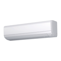
TABLE 5 - MAXIMUM WIRE LENGTHS
WIRE SIZE MAX FEET
16 GA 1225 FT
18 GA 725 FT
20 GA 400 FT
22 GA 200 FT