34 VFD66 User Guide
www.johnsoncontrols.com Issue Number: 2
Auto: Automatically calculates the number of motor poles from the settings of Pr 07
and Pr 39
2P: Set for a 2 pole motor
4P: Set for a 4 pole motor
6P: Set for a 6 pole motor
8P: Set for an 8 pole motor
Ur S: Stator resistance is measured each time the drive is enabled and run
Ur: No measurement is taken
Fd: Fixed boost (V/Hz)
Ur A: Stator resistance is measured the first time the drive is enabled and run
Ur I: Stator resistance measured at each power up when the drive is enabled and run
SrE: Square law characteristic
In all Ur modes, the drive operates in open loop vector mode.
The Fixed boost mode should be used for multiple motor applications.
Determines the boost level when Pr 41 is set to Fd or SrE.
The range is 0.0 to 50% of motor rated voltage.
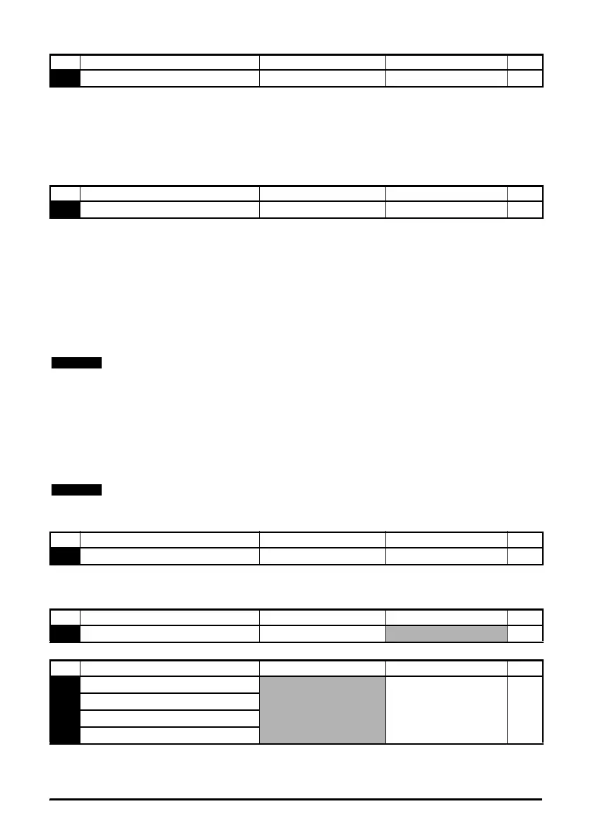
Indicates the last 4 trips of the drive.
No Function Range Defaults Type
40
Number of motor poles Auto, 2P, 4P, 6P, 8P Auto RW
No Function Range Defaults Type
41
Voltage mode select Ur S, Ur, Fd, Ur A, Ur I, SrE Ur A RW
The drive default setting is Ur A mode, which means that the drive will carry out an
autotune the first time the drive is powered up and enabled. If the load is not going to be
stationary when the drive is powered up and enabled the first time, then one of the other
modes should be selected. Not selecting another mode could result in poor motor
performance or OI.AC, It.AC or OV trips.
Once the autotune has been performed successfully in Ur A mode, Fixed boost mode
will then be used.
If the autotune fails i.e. trips on rS, due to no motor being connected, the voltage mode
will then be Ur mode.
No Function Range Defaults Type
42
Low frequency voltage boost 0.0 to 50% 3.0 RW
No Function Range Defaults Type
45
Software version 1.00 to 99.99 RO
No Function Range Defaults Type
55
Last trip
0RO
56 Trip before Pr 55
57 Trip before Pr 56
58 Trip before Pr 57