18 VFD66 User Guide
www.johnsoncontrols.com Issue Number: 2
4.4 Control terminals I/O specification
4.4.1 VFD66 control connections
* Used with class 2 circuits.
4.4.2 Wiring input devices to a VFD66
Connect the appropriate low-voltage input signal device to Terminal Block TB1 (Figure
4-2 on page 12). See Table 4-4 below, Figure 4-6 on page 19, Figure 4-7 on page 19,
and Figure 4-8 on page 20 for additional information on wiring specific Johnson
Controls/PENN™ input devices to the VFD66 controls.
The control circuits are isolated from the power circuits in the drive by basic insulation
(single insulation) only. The installer must ensure that the external control circuits are
insulated from human contact by at least one layer of insulation (supplementary
insulation) rated for use at the AC supply voltage.
If the control circuits are to be connected to other circuits classified as Safety Extra Low
Voltage (SELV) (e.g. to personal computer), an additional isolating barrier must be
included in order to maintain the SELV classification.
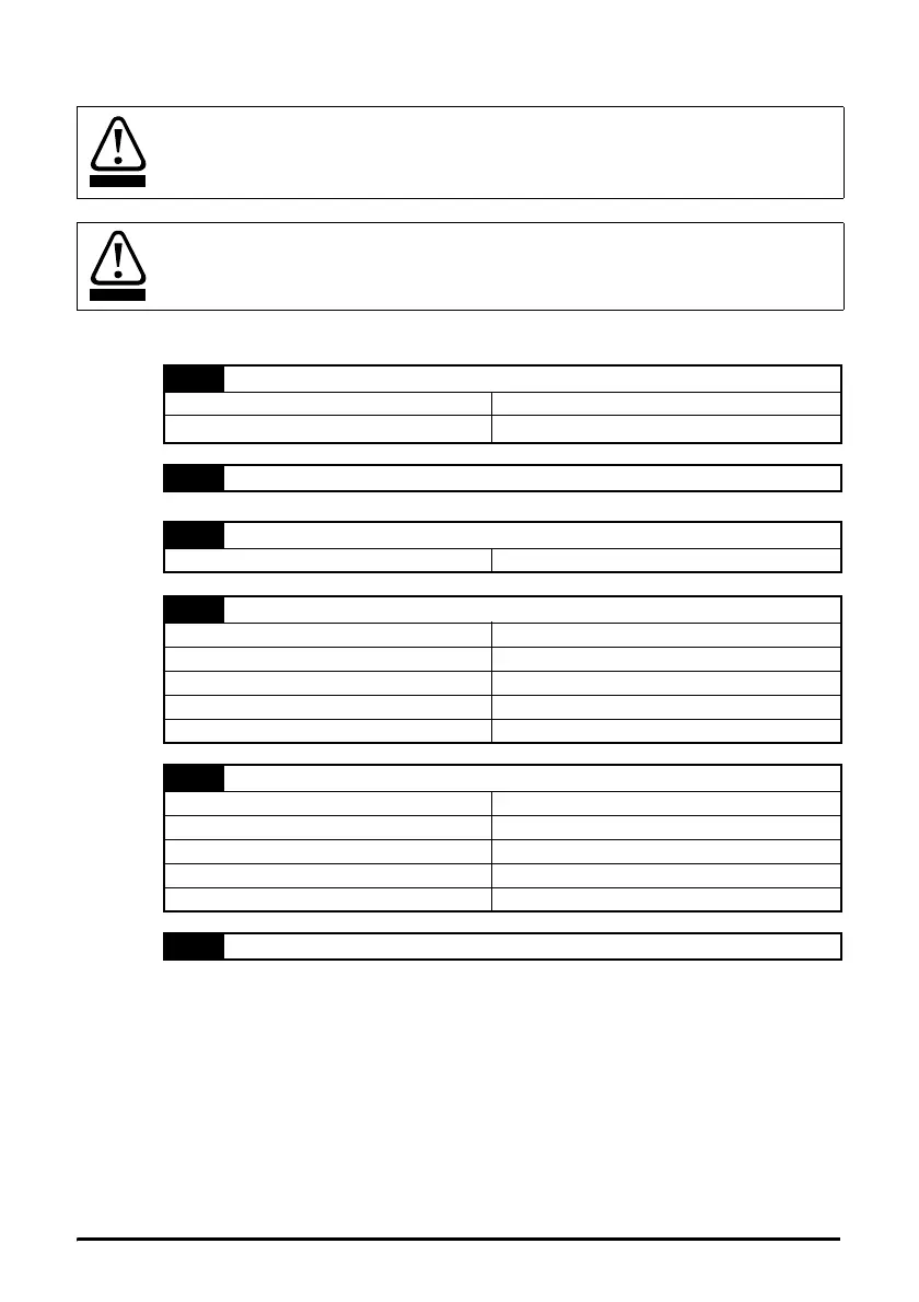
A
Alarm output 1 - drive OK (normally open)*
Voltage rating 5-24Vac or 5-30Vdc
Current rating
100μA at 24V minimum / 200mA maximum
B
Alarm output 2
1
+5V output
Max current rating 20mA (short circuit proof)
2
Analog reference input 1
Voltage 0 to +5V / 0 to +10V
Input impedance 100kΩ
Resolution 0.1%
Accuracy ±5%
Sample time 6ms
3
Analog reference input 2
Voltage 0 to +5V / 0 to +10V
Input impedance 100kΩ
Resolution 0.1%
Accuracy ±5%
Sample time 6ms
4
0V Common