VFD66 User Guide 19
Issue Number: 2 www.johnsoncontrols.com
Safety information Rating data
Mechanical
installation
Electrical
installation
De-rating
Keypad and
display
Parameters Diagnostics
Technical
specifications
UL Listing
Table 4-4 Wiring Johnson Controls/PENN input devices
Input Devices
1
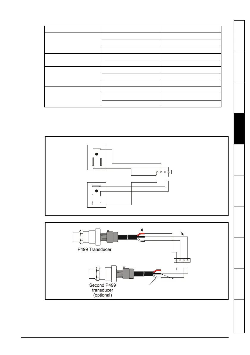
Use terminal 3 to connect an optional second input device to the VFD66 as shown in
Figure 4-6 and Figure 4-7 below.
Figure 4-6 Wiring P35 transducers to VFD66 terminal block TB1
Figure 4-7 Wiring P499 transducers to VFD66 terminal block TB1
Input Device Input Device Terminal VFD66 Control TB1 Terminal
P35AG-9200R Transducer
11
2
2 (or 3)
1
34
C450CPN control module
AO1 2
COM 4
C450CQN control module
AO1 2
AO2 3
COM 4
P499 Series Transducers
Red 1
White
2 (or 3)
1
Black 4
2
1
3
P35 Transducer
Second P35 transducer (optional)
3
421
1
2
3
White
(second output signal)
Red (5 Vdc supply)
White
(output signal)
TB1
Black (common)
Red (5 VDC Supply)
Black
(common)