20 VFD66 User Guide
www.johnsoncontrols.com Issue Number: 2
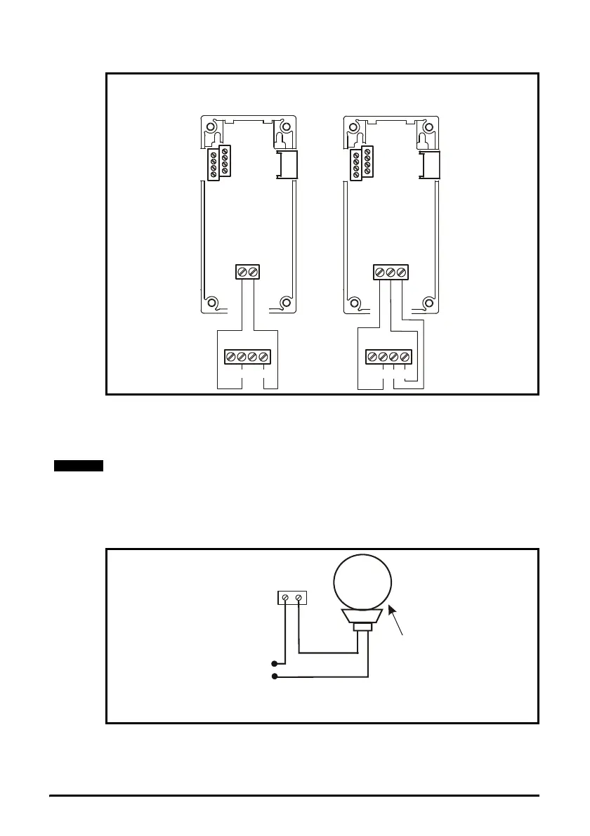
Figure 4-8 Wiring C450CPN control module or C450CQN control module to VFD66
Terminal Block TB1
The VFD66 controls work with most 0 to 5Vdc or 0 to 10Vdc electronic pressure
transducers. For best results, use 0 to 5Vdc, ratiometric P499 Electronic Pressure
Transducers. Ratiometric transducers vary the signal voltage from 10 to 90% of the 5Vdc
supply power as the pressure goes from minimum to maximum of the transducer rating.
4.4.3 Wiring an external alarm to a VFD66 control
The Metal Oxide Silicon Field Effect Transistor (MOSFET) alarm output activates when
a permanent fault condition occurs. See Figure 4-9 below.
Figure 4-9 Wiring the alarm output
Wiring the VFD66 input and output power
Select a wire size for field wiring based on a wire insulation temperature resistance
rating of 75
°C (167°F), with a maximum wire size of 12 AWG. Use only stranded copper
wire, rated for at least 600 volts.
C450CQN
Control module
two analog outputs
AO2
COM
AO1
C450CPN
Control module
one analog output
COM
AO1
2
4
V
C
S
1
C
S
2
C
S
3
5
V
2
4
V
C
S
1
C
S
Applications using a 0 to 10 Vdc transducer must be powered separately.
Device
Alarm output
is rated for 100mA
at 30Vdc / 24Vac
BA
24Vac / 30 Vdc
VFD66 Control
Terminal Block TB1