WT-4000 Series Pneumatic-to-Direct Digital Control (DDC) Room Thermostats Installation Instructions
11
6. Press to confirm the selection.
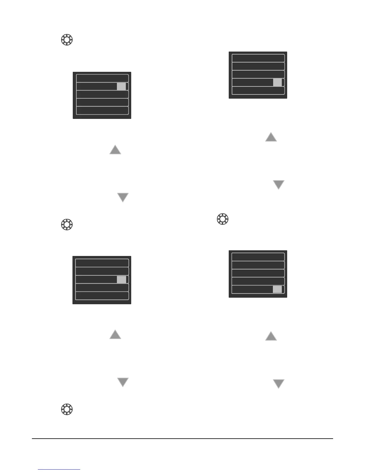
7. Change the setpoint pressure as desired
(Figure 11).
a. Press the Up button to increase the
branch line pressure at setpoint. The valid
range is 1 to 22 psig (7 to 152 kPa), adjustable
in increments of 0.5 psig (3 kPa). The default
setting is 9 psig (62 kPa).
b. Press the Down button to decrease the
branch line pressure at setpoint.
8. Press to confirm the selection.
9. Change the gain/sensitivity as desired
(Figure 12).
a. Press the Up button to increase the
gain/sensitivity. The valid range is 1 to 5 psi/F°
(13 to 65 kPa/C°), adjustable in increments of
0.5 psig (3 kPa). The default setting is 2 psi/F°
(26 kPa/C°).
b. Press the Down button to decrease the
gain/sensitivity.
10. Press to confirm the selection.
11. Change the proportional band – proportional
range/throttling range as desired (Figure 13).
a. Press the Up button to increase the
proportional band – proportional range/
throttling range. The valid range is 0 to 10F°
(0 to 6C°), adjustable in increments of 1F°
(0.6C°). The default setting is 6F° (3.6C°).
b. Press the Down button to decrease the
proportional band – proportional range/
throttling range.
12. Press to confirm the selection.
13. Change the unoccupied mode pressure as
desired (Figure 14).
a. Press the Up button to increase the
branch line pressure during Unoccupied Mode
periods. The valid range is 0 to 22 psig (0 to
152 kPa), adjustable in increments of 0.5 psig
(3 kPa). The default setting is 0 psig (0 kPa).
b. Press the Down button to decrease the
branch line pressure during Unoccupied Mode
periods.
FIG:drct_actng
9.0
Gain
2.0
PropBnd
6.0
UnocPsi 0.0
DirActing
Figure 11: Changing the Setpoint Pressure
FIG:gain
UnocPsi
Figure 12: Changing the Gain/Sensitivity
FIG:prprtnl_bnd
SPPsi
9.0
Gain
2.0
PropBnd
6.0
UnocPsi 0.0
DirActing
Figure 13: Changing the Proportional Band –
Proportional Range/Throttling Range
FIG:unoccpd_mde_prssr
SPPsi
9.0
Gain
2.0
PropBnd
6.0
UnocPs i
Figure 14: Changing the Unoccupied Mode
Pressure