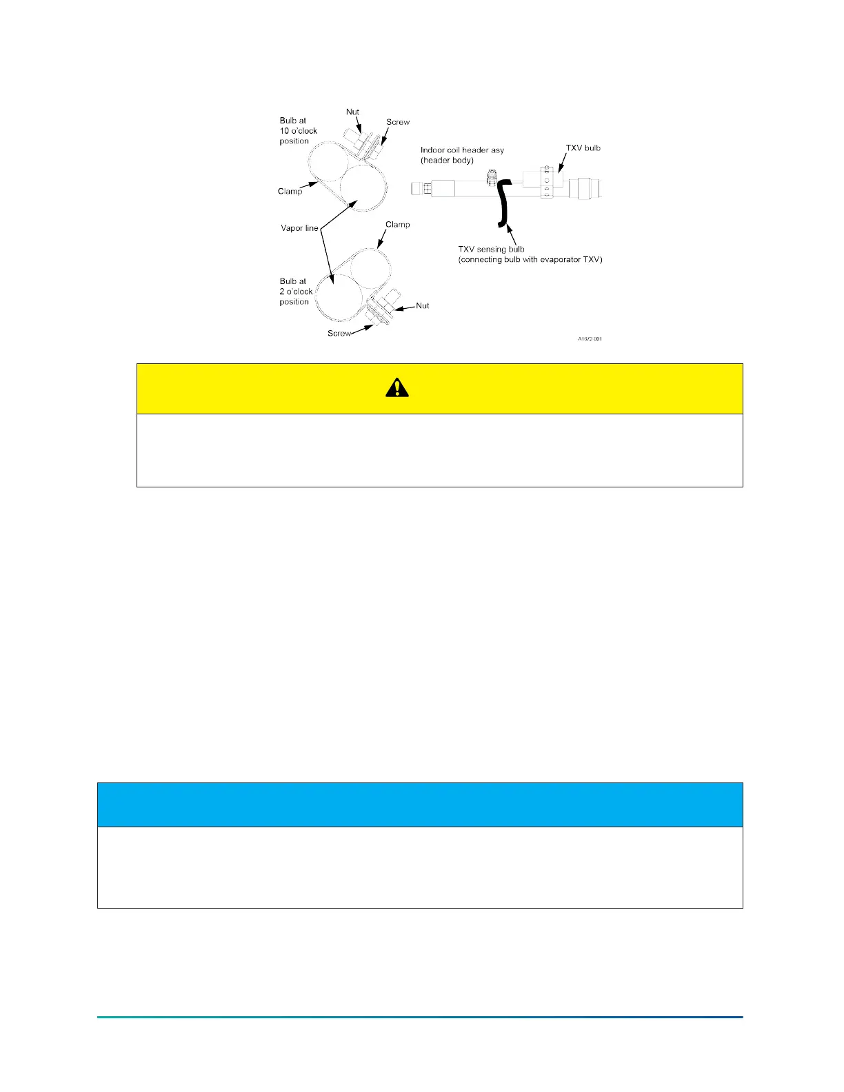
Figure 12: Correct bulb location for TXV
CAUTION
Outdoor unit model numbers ending with an H have a factory installed hard start kit which
is required when a TXV kit is installed. Outdoor unit model numbers with no H ending do not
require a hard start kit unless local regulations dictate it.
7. Route the temperature sensing bulb tube for the TXV toward the vapor line header and the
TXV equalizer tube connection port on the vapor line header.
8. Install the TXV bulb to the vapor line near the TXV equalizer tube connection port, using the
bulb clamps supplied with the TXV assembly. Ensure that the bulb makes maximum contact.
See Figure 11 and Figure 12 and adhere to the following:
a. Install the TXV bulb on the vapor line suction header near the TXV equalizer tube
connection port. Ensure that the bulb is installed at a 10 o’clock or 2 o’clock position.
b. Insulate the TXV bulb using the thermal insulation provided to protect it from the effect of
the surrounding ambient temperature. Cover the bulb completely to insulate it.
What to do next:
After the refrigerant piping is installed, leak test the system.
Checking for refrigerant leaks
About this task:
NOTICE
Pressurize the refrigerant piping and the indoor coil to 250 psig with dry nitrogen and leak test with a
bubble type leak detector. Then release the nitrogen charge.
Do not use the system refrigerant in the outdoor unit to purge or leak test.
1. Pressurize the refrigerant piping and the indoor coil to 250 psig with dry nitrogen.
Installation Manual: R-454B Outdoor Split-System Air Conditioner30
Johnson Controls Ducted Systems