NOTICE
A Start Assist Kit is available and recommended for long refrigerant piping applications or in
areas of known low voltage problems. The kit may be required when a TXV is used (refer to the
Tabular Data Sheet to determine if applicable).
5. Mount the thermostat about 5 ft above the floor, where it is exposed to normal room air
circulation. Do not place it on an outside wall or where it is exposed to the radiant effect from
exposed glass or appliances, drafts from outside doors or supply air grilles.
6. Route the 24 V control wiring (NEC Class 2) from the outdoor unit to the indoor unit and
thermostat.
NOTICE
To eliminate erratic operation, seal the hole in the wall at the thermostat with permagum or
equivalent to prevent air drafts affecting the operation of the thermostat.
NOTICE
Check that cabling will not be subject to wear, corrosion, excessive pressure, vibration, sharp
edges, or any other adverse environmental effects. During the check, consider the effects of
aging or continual vibration from sources such as compressors or fans.
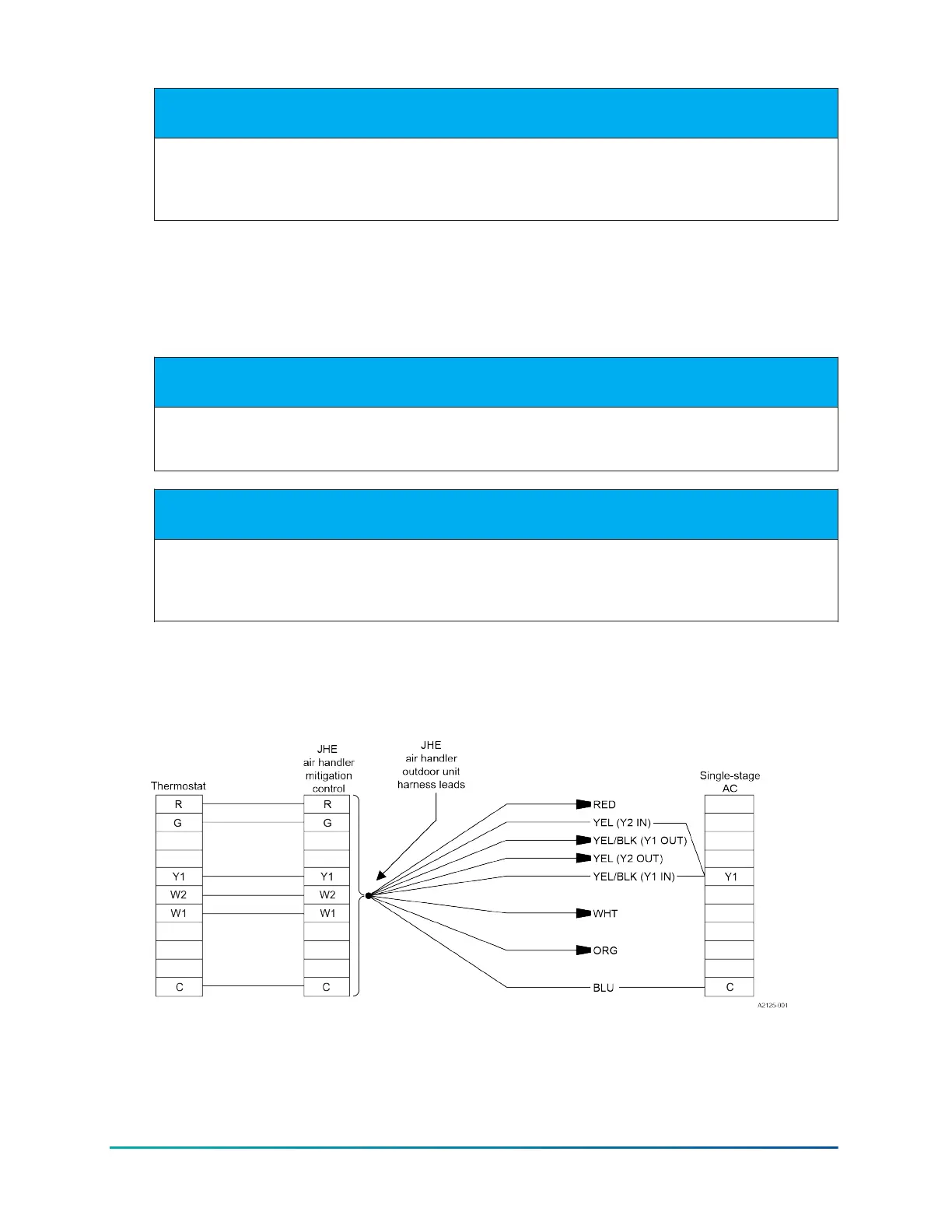
Control wiring
Figure 17: Control wiring - standard ECM air handler and standard single-stage air
conditioner - conventional wiring
Installation Manual: R-454B Outdoor Split-System Air Conditioner36
Johnson Controls Ducted Systems