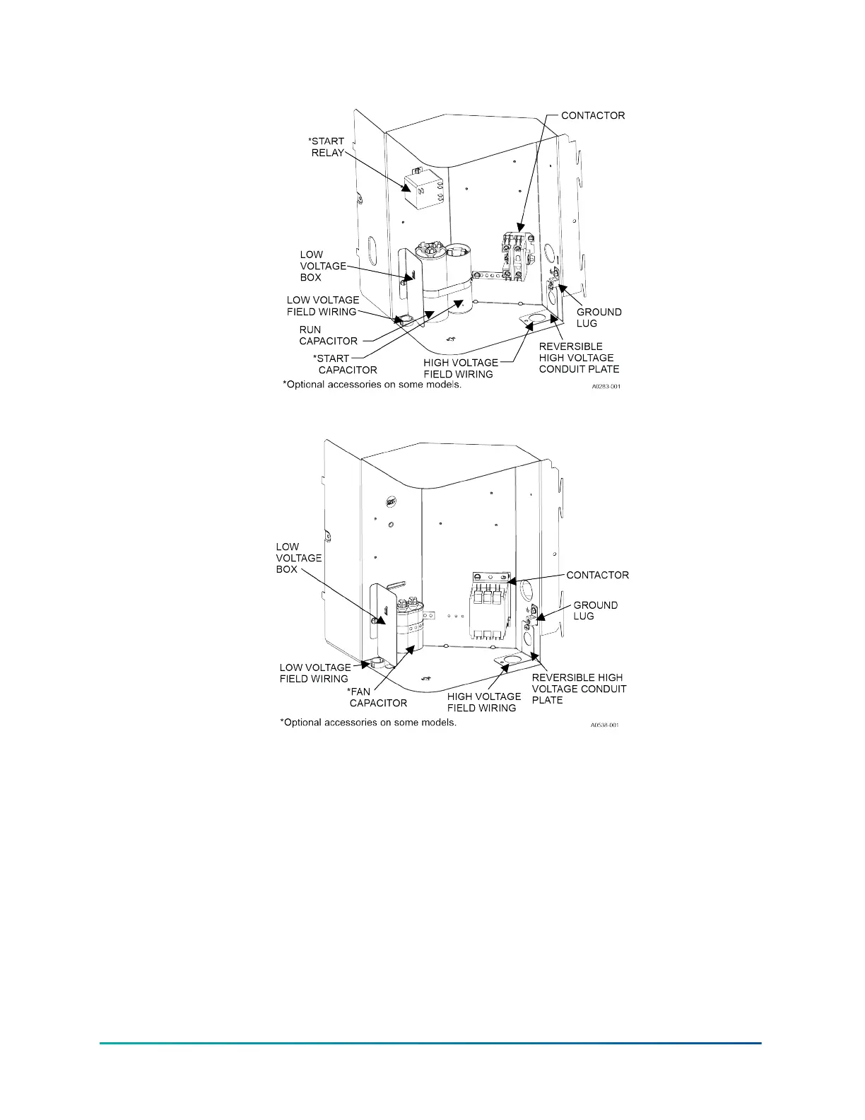
Figure 15: Outdoor unit control box (single-phase - larger base)
Figure 16: Outdoor unit control box (three-phase - larger base)
Completing the field control wiring connections
1. Route low voltage wiring into bottom of control box as shown in Figure 14 or Figure 15. Make
low voltage wiring connections inside the low voltage box as shown in Figure .
2. The complete connection diagram and schematic wiring label is located on the inside surface
of the unit service access panel.
3. Replace the control box cover removed in Step 2 of the procedures.
4. All field wiring to be in accordance with national electrical codes (NEC) or local city codes.
35Installation Manual: R-454B Outdoor Split-System Air Conditioner
Johnson Controls Ducted Systems