SM-18003
5-9
EXTERNAL INPUT/OUTPUT AND FUNCTION SETTING
NOTES:
1.Pickingupsignalwithin10secondsafterpowersupplyisturnedONisnotpossibleduetoinitializingof
components.
Donotchangethesignal(ON/OFF)inthisperiod.
2.WiredControllerisrequiredforthisfunction.
3.ThefollowingON/OFFfunctionsarenotavailableafterthemanual(forced)stoppagebecausecommands
fromthewiredcontrollerarecanceled.
a.ON/OFFfunctionfromaremoteplace
b.ON/OFFfunctionbythecentralizedcontrollerwhilethewirelesswiredcontrollerisused.
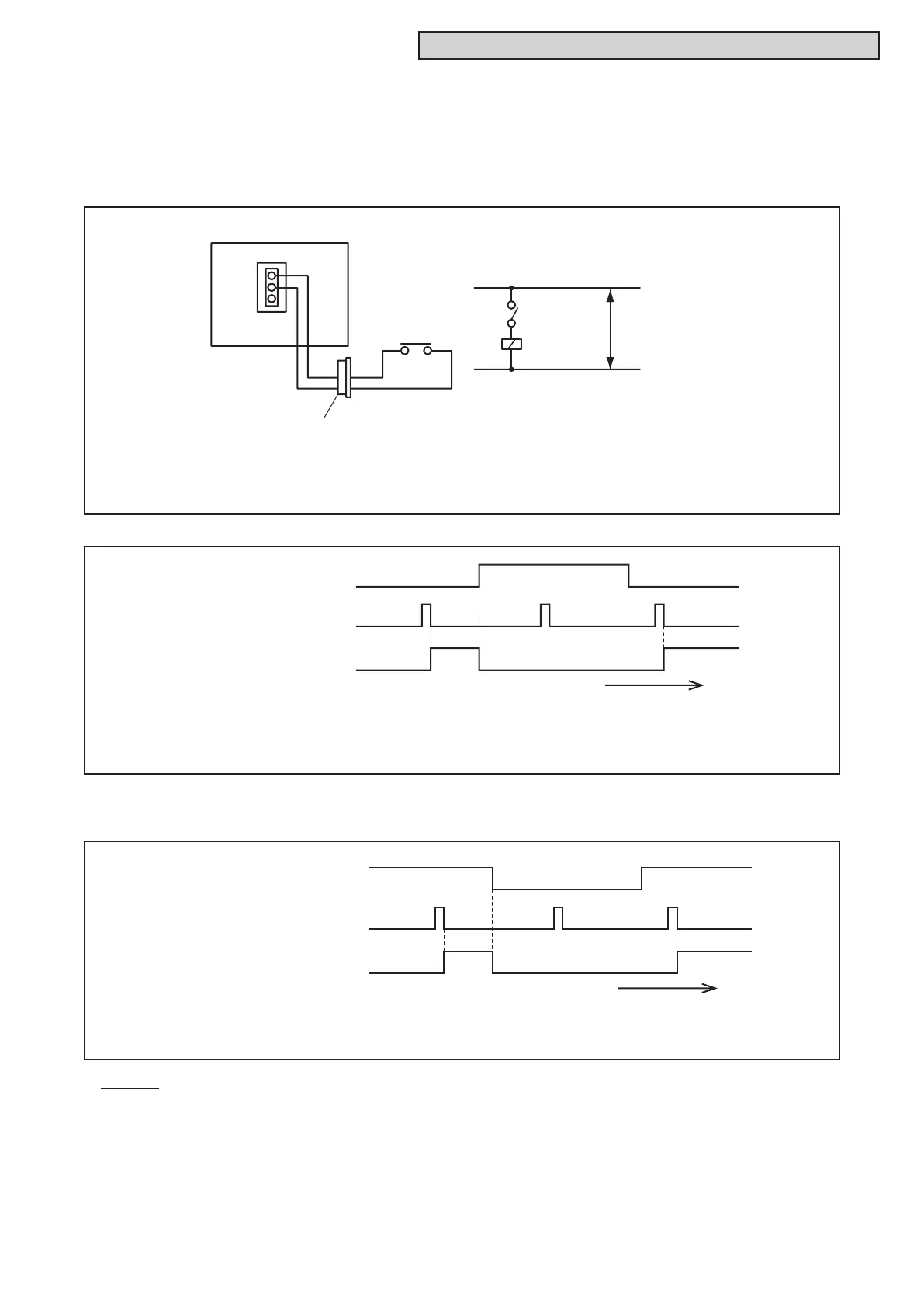
(
SS3
X1
Power
Source
CN3
X1
3P Connector
3
2
1
3
2
SS3: Forced Stoppage Sw.
Wiring Diagram Example
Example: Forbidding Remote Control after Manual (Forced) Stoppage
is set to terminals 2 and 3 of CN3.
Signal to terminals 2 & 3 of CN3
Control by Wired Controller
Unit Operation
Time Chart
Ti
Example: Forbidding Remote Control after Manual (Forced) Stoppage
is set to terminals 2 and 3 of CN3.
(4) ForbiddingRemoteControlafterManual(Forced)Stoppage(LevelSignalInput)
[InputSetting:Code(06)]
Byusingthesignalfromabuildingmanagementsystem,theindoorunitscanbestoppedandthe
individualcommandsfromthewiredcontrollerarecanceled.Anexampleofbasicwiringandtime
chartisshownbelow.
ThisfunctioncanbeusedforBcontactsifusing“SelectionofForcedStoppageLogic”inSection5.4.2.1
“FunctionSelectionItem.”Anexampleoftimechartisshownbelow.
Signal to terminals 2 & 3 of CN3
Control by Wired Controller
Unit Operation
Time Chart
Ti
me
(Example: Setting for B Contacts)
 Loading...