YCRE
4-10
035-21786-100 Rev. 1 (0909)
N
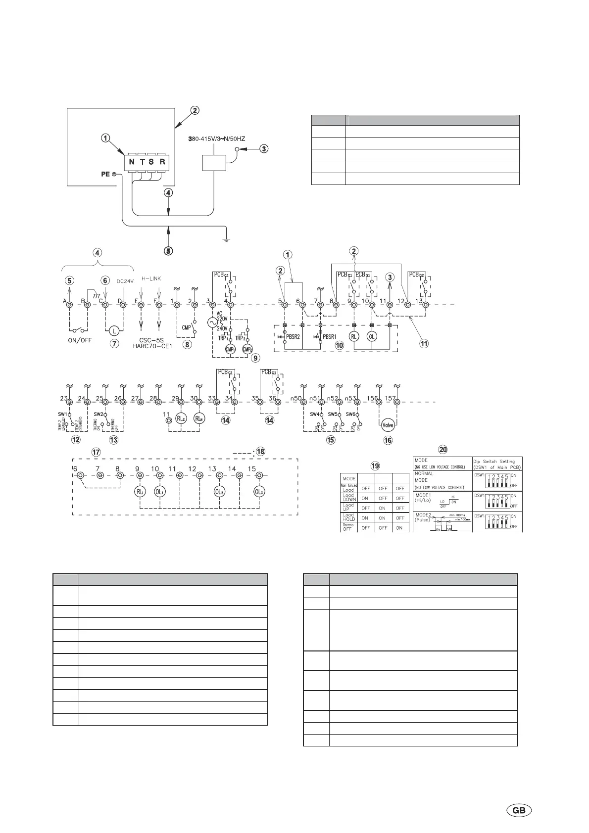
Name
1
In case of remote control operation this wire
must be removed (using item 10).
2 S Phase
3 Neutral
4 Low Voltage / Remote Control
5 Run/Stop Signal
6 Alarm Signal
7 Alarm Lamp (30mA max)
8 Pump Interlock
9 Pump operation
10 Remote Control Switch (RSW-A) (OPTION)
11 2 cycles
N
Name
12 2nd. Setting Temperature
13 External Thermostat Operation
14
Only used for:
- Diff. Water Pressure switch (OPTION)
- Flow Switch (OPTION)
For Air Cooled: Link 35/36
15
Force Compressor
Load Operation
16
Free Cooling
Output signal (Only cycle Nº 1)
17
In case of individual indication without Remote
Control Switch
18 Customer wiring
19 Force compressor load
20 Setting of low voltage control
NOTE
:
1. All the setting must be performed before Power ON.
2. Remote / Local Change over Switch on Operation Switch must be set, to Remote
3. Terminals 1 ~ 57 are for AC220-240V,Te rminals A ~ D are for DC24V. Terminals E ~ F are H-link (Low si
nal)
N°
Name
1 Main Power/Terminal Board (R,S,T,N)
2 Electrical Box
3 Main Power Switch
4 Main Power Wiring
5 Earth Wiring
The main connection to terminal N is required.
Remove link between 5 and 6
when remote control switch
option is fitted
DSW1-4 must be set to ON when
remote control switch option is fitted
EVAP
NOTES:
30mA max
SW4
SW5 SW6

 Loading...


