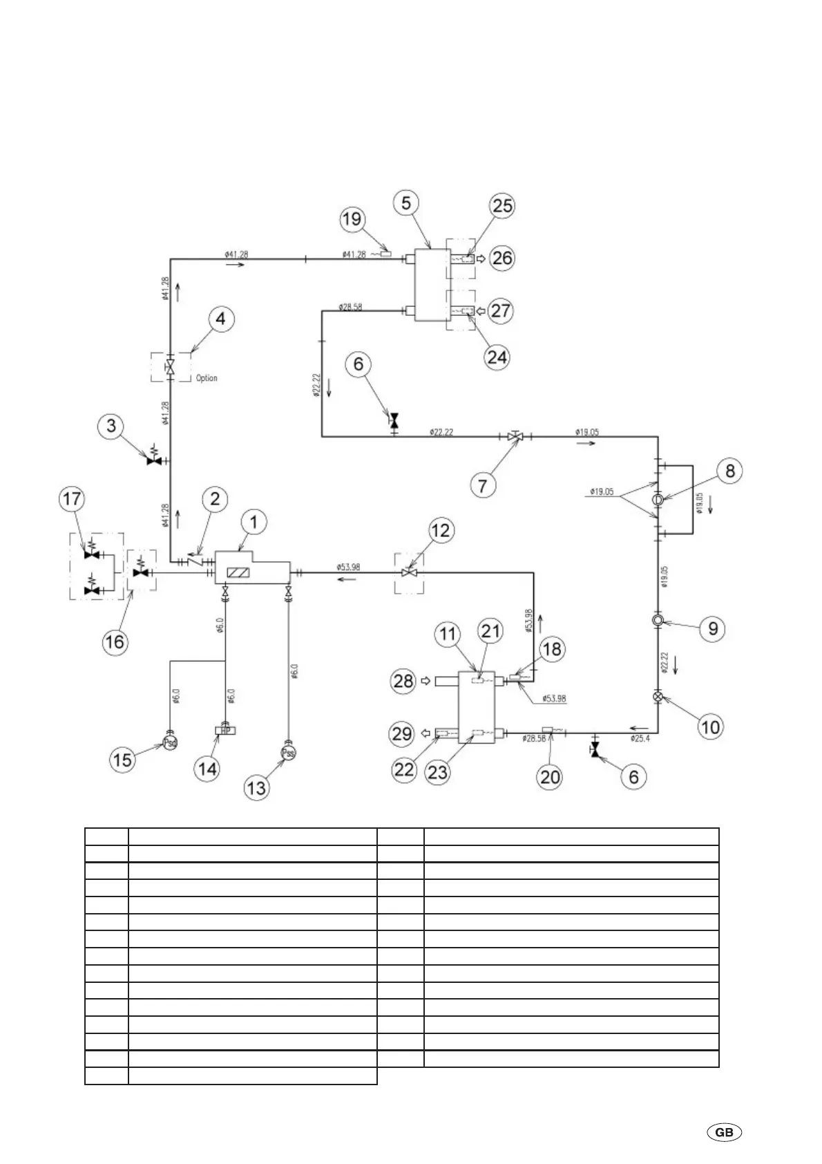
2.9 Refrigerant Flow Diagram
YCSE 040, 050, 060, 100 Models
2-4
035-21786-100 Rev. 1 (0909)
1 Compressor 16 Compressor Safety Valve (Option)
2 Check Valve 17 Compressor Dual Safety Valve (Option)
3 Pressure Relief Valve 18 Thermistor - Suction
4 Stop Valve (Option) 19 Thermistor - Discharge
5 Condenser 20 Thermistor - Evaporator
6 Stop Valve - Refrigerant Charge Point 21 Thermistor - Evaporator Water Inlet
7 Stop Valve 22 Thermistor - Evaporator Water Oulet
8 Drier 23 Thermistor - Evaporator Water Oulet
9 Sight Glass 24 Thermistor - Condenser Water Inlet (Option)
10 Electronic Expansion Valve 25 Thermistor - Condenser Water Outlet (Option)
11 Evaporator 26 Condenser Water Outlet
12 Stop Valve (Option) 27 Condenser Water Inlet
13 Low Pressure Sensor 28 Evaporator Water Inlet
14 High Pressure Switch 29 Evaporator Water Outlet
15 High Pressure Sensor

 Loading...


