6 UNIT OPERATION
6.1 General Description
The units are designed to work independently, or in
conjunction with other equipment via a building
management system or other automated control
system. When operating, the unit controls monitor the
chilled liquid system temperature at the unit and take the
appropriate action to maintain this temperature within
desired limits. This action will involve running one or
both compressors at a suitable load to match the cooling
effect of the refrigerating systems to the heat load on the
liquid system. The heat removed from the chilled liquid
is then rejected via the water cooled condenser. The
following sections give an overview of the operation of
the unit.
6.2 Operation
The operating sequence described below relate to
operation on a cooling demand start after power has
been applied, such as start-up commissioning.
The controller will perform a pre-check to ensure that
any remote interlocks will allow the unit to run, all safety
cut-outs are satisfied and that cooling load is required
(i.e. that the chilled liquid temperature is outside the set
limits). Any problems found by the pre-check will be
displayed if present. If no problems are present and
cooling duty is required the compressor will start.
6.3 Normal Running and Cycling
Once the unit has been started, all operations are fully
automatic. The display will show one of the normal
operation codes as detailed in the following table.
When a compressor is running the controller monitors
various system parameters. Should any problems
occur, the control system will immediately take
appropriate action and display the nature of the fault
Refer to Alarm Codes tables for further details.
6.4 Shutdown
The unit can be stopped manually at any time by
pressing the system OFF switch SW2.
To prevent damage to the unit the control
supply to the compressor heaters should not
be switched off, even when the unit is not
required to run.
If mains power must be switched off, (for extended
maintenance or a shutdown period), the compressor
suction, discharge and liquid line service valves on both
systems should be closed and if there is a possibility of
liquid freezing due to low ambient temperatures, the
cooler and condenser should be drained. Fit
appropriate valve tags to indicate valve positions and
that systems are drained and isolators. The valves
should be opened, the cooler and condenser refilled
and the power must be switched on for at least 12 hours
before the unit is restarted.
6.5 Control System
The control system comprises the operator control
panel and display on the front of the unit and a control
printed circuit board located inside the unit on the rear of
the control panel.
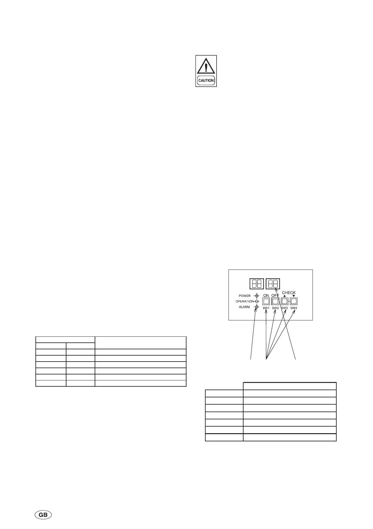
6.5.1 Control Panel
The control panel comprises four push-button switches,
a four figure display and three LEDs.
The control panel has four modes of operation:
n
Normal
n
Alarm
n
Parameter settings
n
Second Water Temperature Setting
6-1
035-21786-100 Rev. 1 (0909)
Display
LEDs
Push
Button
witches
Function
SW1 Sets system ON
SW2 Sets system OFF
SW3 Display control UP
SW4 Display control DOWN
Power LED Displays red when power is present
Alarm LED Display orange when alarm occurs
Display Displays operating or alarm codes
No. 1 Comp. No.2 Comp.
C1-88 C2-88 Power supply present, System off
C1-Co C2-Co Unit in Cooling mode
C1-HE C2-HE Heating mode (heat pump option only)
C1-oF C2-oF Unit off - no cooling demand
Pu Pu Pump only operation
C1-E0 C2-E0 Initialising Electronic Expansion Valve
Display Code
Function

 Loading...


