5566019-BIM-B-1118
22 Johnson Controls Ducted Systems
Thermostat wiring
Note: This section is not applicable to units with a VFD.
Install the thermostat on an inside wall approximately 56 inches
above the floor. The thermostat must not be subject to drafts,
sun exposure, or heat from electrical fixtures or appliances.
Follow the manufacturer's instructions enclosed with thermostat
for the general installation procedure. Use color-coded,
insulated wires to connect the thermostat to the unit. See Table
12 for control wire sizing and maximum length.
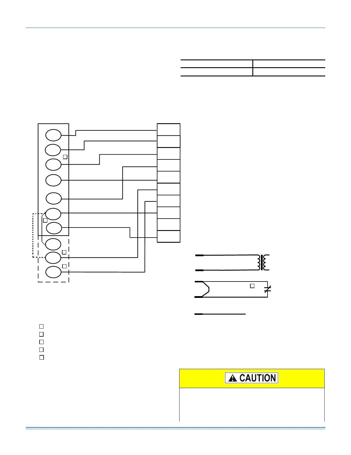
Figure 24: Typical electronic thermostat field wiring
Table 12:Control wire sizes
Wire size Maximum length
1
1. From the unit to the thermostat and back to the unit.
18 AWG 150 feet
OCC
C
RC
G
Y2
Y1
W2
W1
X
R
THERMOSTAT
TERMINALS
CONTROL
TERMINAL
BLOCK
TERMINALS ON A
LIMITED NUMBER
OF THERMOSTATS
1
4
3
1
2
4
Second stageŚĞĂƟŶŐŶot required on single stage heĂƟŶg units.
Jumper is required if there is no Smoke Detector circuit.
Jumper is required for any coŵďŝŶĂƟŽŶ of R, RC, or RH.
5
5
OCC is an output from the thermostat to indicate the Occupied ĐŽŶĚŝƟon.
X is an input to the thermostat to display Error Status condiƟons.
3
W2
Y1
G
OCC
Y2
X
R
SD-24
C
W1
2
24V
C
24 VAC
Class 2
SD-24
Jumper Located on Harness
Smoke
Detector
SD-R
24V Output
R
(If No Smoke Detector)
(If Smoke Detector Is Used)
R~Occ Jumper:
Smart Equipment Control boards come from the
factory with a jumper wire between R and OCC
terminals on the thermostat terminal strip. Failure
to remove this jumper will place the unit into the
Occupied mode no matter what the occupancy
demand is from the thermostat or EMS system.
To allow Thermostat or EMS control of the
Occupied mode for the unit, this jumper must be
removed during commissioning.
208/230-3-60 and 380/415-3-50 units control
transformers are factory wired for 230v and 415v power
supply respectively. Change the tap on the transformer
for 208-3-60 or 380-3-50 operation. See the unit wiring
diagram.