10
T500 Series Non-Programmable Thermostats Product/Technical Bulletin
Heat/Cool: 2 Minute
(Minimum On/Off)
Keyboard Unlocked
Fan immediate with
a call for heat
Single Stage
LED 1 Icon Off
LED 2 Icon Off
Fan on with plenum
switch
Multi-stage
LED 1 Icon
(Filter)
LED 2 Icon
(Wrench/Fault)
ON
1
3
2
4
5
6
Keyboard Locked
Heat/Cool: 4 Minute
(Minimum On/Off)
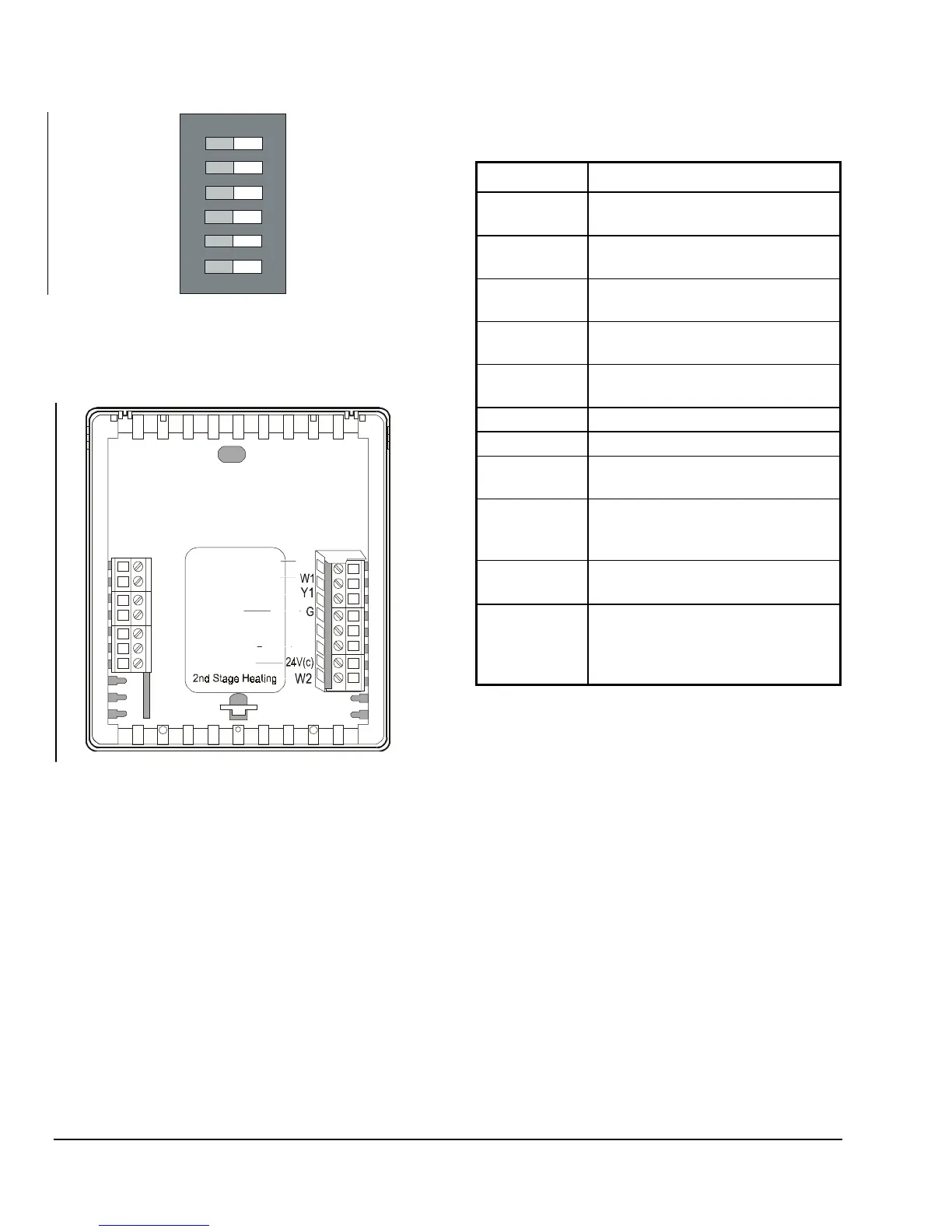
Figure 11: T500MSN-1 Factory-Set DIP Switch
Settings
LED1
LED2
CLK1
CLK2
RS2
RS1
2nd Stage Cooling
1st Stage Heating
1st Stage Cooling
Fan
24V
R
Y2
Common
MSN-1Wire
RS+V
24VAC
Figure 12: T500MSN-1 Wiring Configuration
Table 6: T500MSN-1 Output Terminal
Designations
Terminal Function
W2
Energizes on a call for second-stage
heat
Y2
Energizes on a call for second-stage
cooling
W1
Energizes on a call for first-stage
heat
Y1
Energizes on a call for first-stage
cooling
G
Energizes fan on call for heating or
cooling or by pressing the
Fan
button
R
Independent switching voltage
24V
24 VAC from equipment transformer
24V(c)
24 VAC (common) from equipment
transformer
LED 1
LED 2
Input connection that energizes
LED 1 or LED 2 from remote status
device (See Figure 12 and Table 7.)
CLK1
CLK2
Connections for remote clock/timer
for alternate setpoints
RS2
RS1
RS+V
Connection for outdoor temperature
sensor and/or indoor remote sensor
option; refer to instructions included
with sensors
 Loading...