12
T500 Series Non-Programmable Thermostats Product/Technical Bulletin
Remote
Clock/Timer
(if used)
Remote
Sensor
(if used)
Thermostat
Equipment
T1
T2
Field Contact Switches
2nd Stage
Compressor
Electronics
Y1 Y2 G O B R
CLK1
CLK2
24V(c)
RS+V RS1 RS2
LED2
24V
Reverse
Valve
Heating
Reverse
Valve
Cooling
Fan
1st Stage
Compressor
1st Stage
Auxiliary
LED1W1
HPN-1
Optional
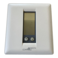
If the transformer (T2) is to power all of the loads
R and 24V must be connected by inserting jumper J 1
located above the relays. If a separate 24V transformer
(T1) is to be used remove the jumper J 1 to disconnect R and 24V(c).
P
P
J1P
Figure 14: T500HPN-1 Wiring Schematic
Remote
Clock/Timer
(if used)
Remote
Sensor
(if used)
Thermostat
Equipment
T1 T2
Field Contact Switches
2nd Stage
Cool
Electronics
Y1
Y2
G
R
CLK1
CLK2
24V(c)
RS+V
RS1
RS2
LED2
24V
Fan
2nd Stage
Heat
LED1
W2
W1
1st Stage
Cool
Optional
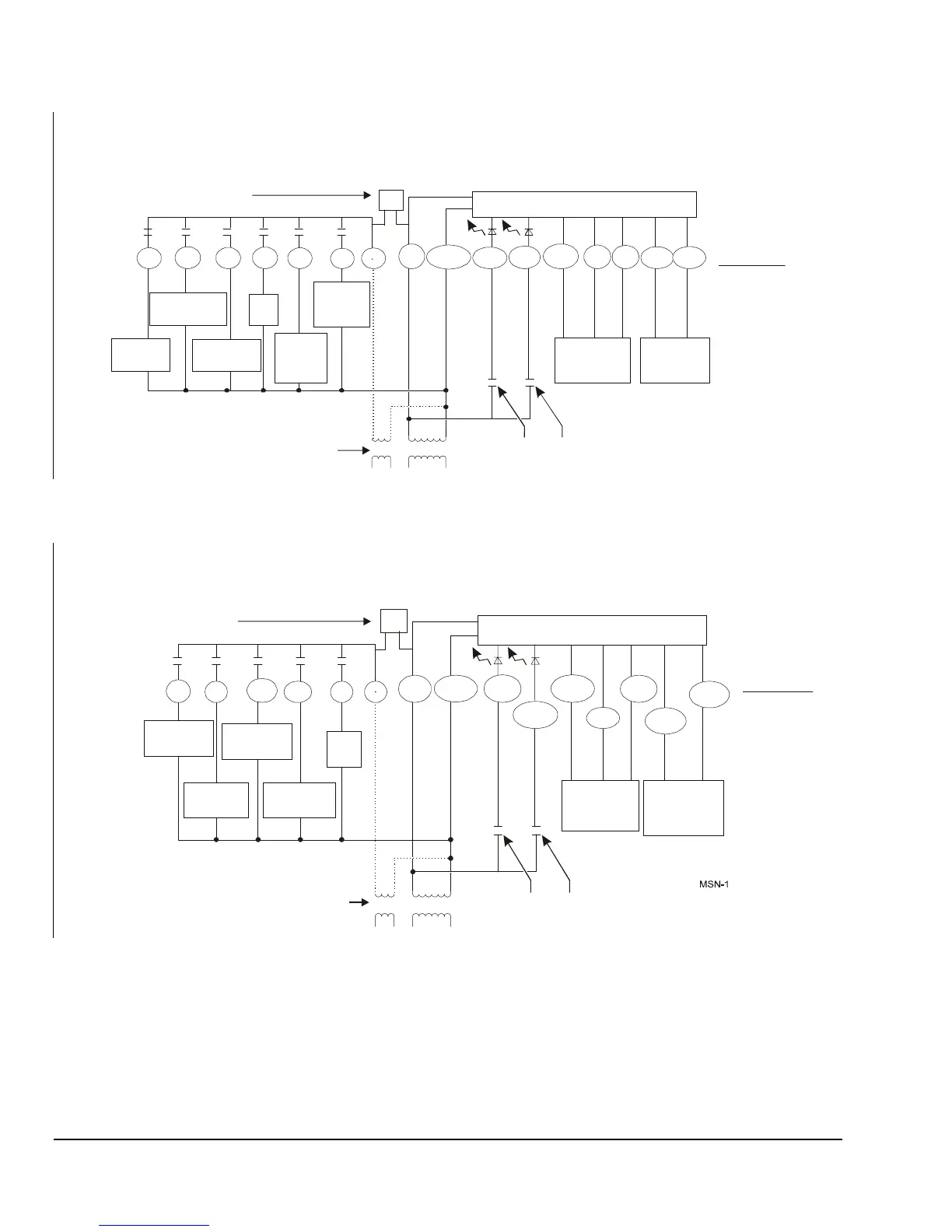
If the transformer (T2) is to power all of the loads R and 24V
must be connected by inserting jumper J 1 located above
the relays. If a separate 24V transformer (T1) is to
be used, remove the jumper J 1 to disconnect R and 24V(c).
P
P
JP1
1st Stage
Heat
Figure 15: T500MSN-1 Wiring Schematic
 Loading...