8
T500 Series Non-Programmable Thermostats Product/Technical Bulletin
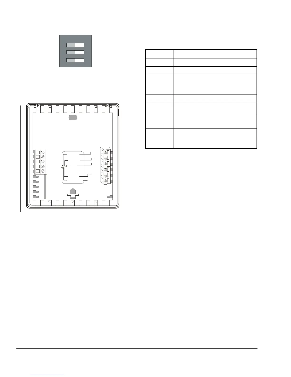
Keyboard LockedKeyboard Unlocked
ON
1
3
2
Fan Immediate
with Call for Heat
Heat/Cool: 4 Minute
Minimum On/Off
Heat/Cool: 2 Minute
Minimum On/Off
Fan On with Plenum
Temperature Switch
Figure 7: T500HCN-1 Factory-Set DIP Switch
Settings (All Off)
CLK1
CLK2
RS2
RS1
W1
Y1
G
R
24V
24V(c)
Heating
Cooling
Fan
Common
Hcn-1wire
RS+V
24VAC
Figure 8: T500HCN-1 Wiring Configuration
Table 4: T500HCN-1 Output Terminal
Designations
Terminal Function
W1
Energizes on call for heating
Y1
Energizes on call for cooling
G
Energizes fan on call for heating or
cooling or by pressing the
Fan
button
R
Independent switching voltage
24V
24 VAC from equipment transformer
24V(c)
24 VAC (common) from equipment
transformer
CLK1
CLK2
Connections for remote clock/timer for
alternate setpoints
RS2
RS1
RS+V
Connections for outdoor air temperature
or indoor remote sensors; refer to
instructions included with sensors
 Loading...