MA4:3
V Range 502 l 652 l 802 Maintenance Manual
Johnston Sweepers Limited
Chapter - Water System
The assembly of the twin diaphragm pump is quite simple and straightforward, but attention to the
under mentioned points will afford economy by prolonging the life of the pump and, more especially,
the expendable components.
1 Diaphragms -
When replacing a diaphragm, turn the crankshaft until the relative connecting rod is at TDC
so that when securing the diaphragm and the tension pad by means of the tension pad bolt,
the periphery of the diaphragm is free of the crank case.
Ensure that the tension pad is pulled down onto the connecting rod.
2 Pump Chambers -
Before fitting a pump chamber, turn the crankshaft until the relative diaphragm is at the
centre of its stroke, i.e. so that the periphery of the diaphragm is just resting on the face of
the crankcase. Place the pump chamber in position, place the bolts and nuts in position and
tighten ‘finger tight’. Tighten down, but make sure that the pump chamber is pulled down
square so that the lower face of the chamber is correctly located against the crankcase.
3 Manifolds and Valves -
Fit the valve sealing rings onto the valve seat. Place the delivery valve (stem upwards) over
the delivery orifice of the pump chamber and push the sealing ring down so that it is flush
with the pump chamber. Fit the suction valves in a similar manner, but with stem downwards.
Place the manifold over the valves and see that it sits square. If the manifold does not
sit square, then either the valves or the sealing rings are not correctly located. Place the
securing bolts in position and pull down squarely.
It is important that these instructions are carried out, especially with regard to the fitting of the
manifolds, to ensure a satisfactory seal at the valve sealing rings. Unless these instructions are
followed, leakage will be experienced at the joint between the manifold and the pump chambers. On
dismantling a pump for examination, if the valve sealing rings have taken on a permanent set to their
location (roughly triangular in cross section), they should be replaced.
M02MA-029
A
E
D
F
G
H
J
K
B
C
L
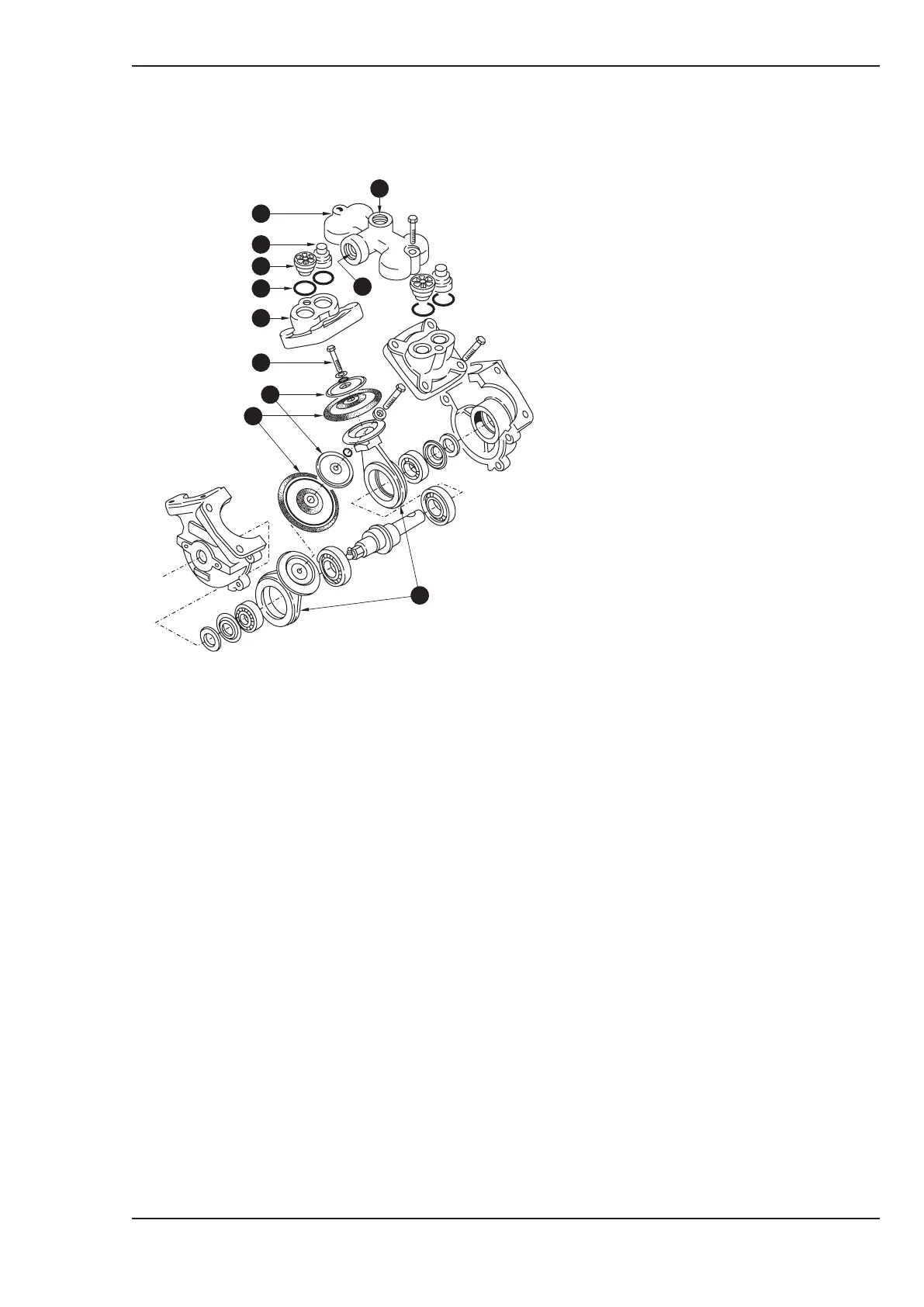
KEY
(A) Manifold
(B) Suction Port
(C) Delivery Port
(D) Suction Valve
(E) Delivery Valve
(F) Valve Sealing Rings
(G) Pump Chamber
(H) Tension Pad Bolts
(J) Tension Pads
(K) Diaphragms
(L) Connecting Rods
Water Pump
COMPONENT MAINTENANCE AND SETTINGS