V Range 502 l 652 l 802 Maintenance Manual
MA4:4
Chapter - Water System
M02MA-030
A
C
B
M02MA-018
A
C
F
B
D
E
M02MA-013
A
C
B
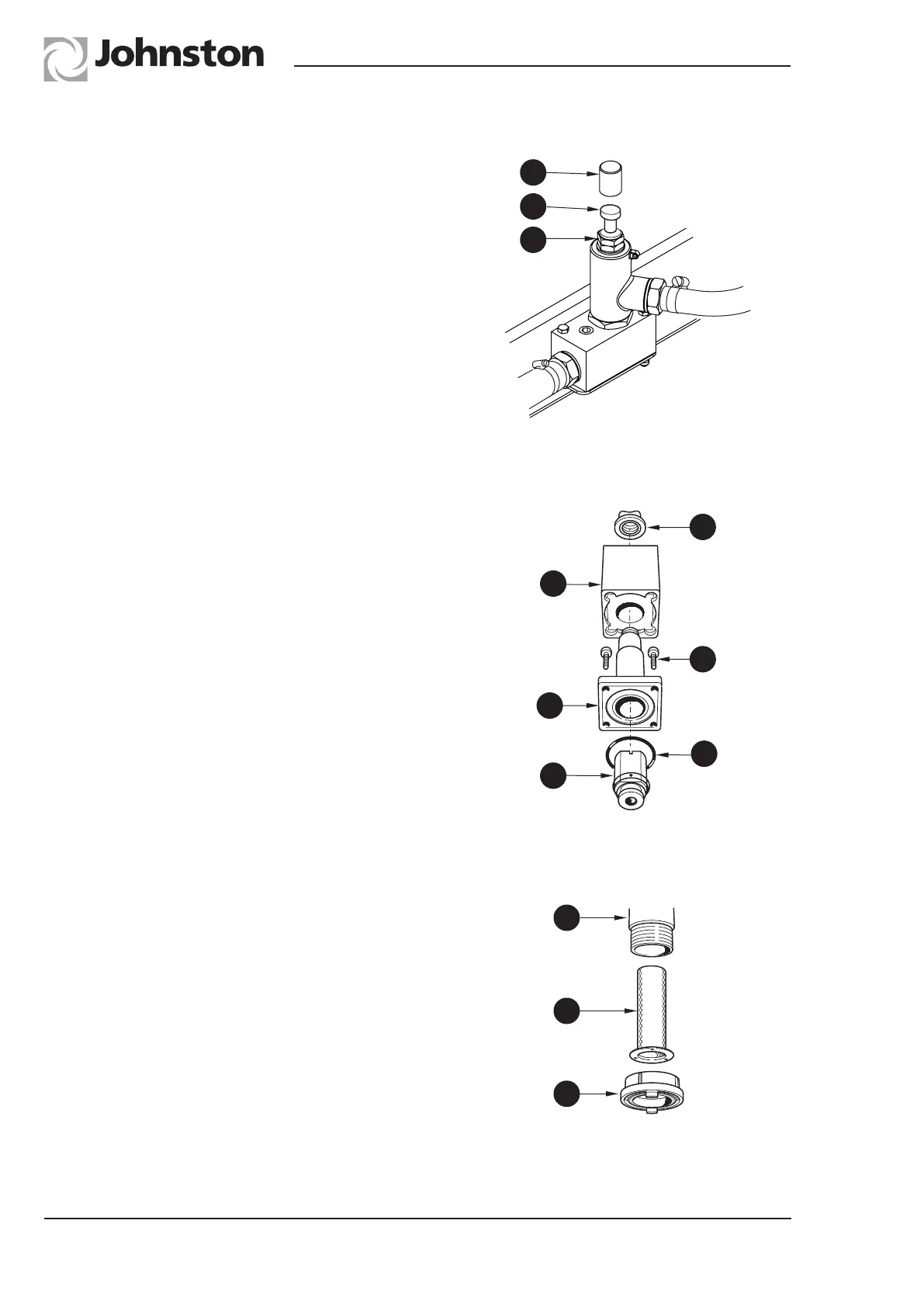
This valve is factory set and should not normally
be touched, but should it be necessary to make
adjustments, the pressure is set as follows.
Pressure Setting
Remove the cover (A) and loosen adjuster
locknut (B). Connect a pressure gauge to the
test point located in the systems locker. With
the auxiliary engine running at low idle speed
(750/800), and all water sprays switched off,
turn adjuster screw (C) until gauge reads
3.5 bar (50 psi). Tighten locknut and replace
cover.
Solenoid valves control the water spray jets
and are located in the systems locker.
The valve is easily dismantled for inspection or
cleaning by unscrewing the retaining cap (A)
through the coil (B).
To access the armature, unscrew the four
retaining screws (C) and remove the armature
cover (D). The armature (E) can be removed.
When refitting parts ensure the ‘O’ ring (F) is in
good condition and located correctly.
Periodically the hydrant filter (A) should be
cleaned, or replaced if damaged. To gain
access to the filter, unscrew the hydrant
coupling (B) and withdraw the filter from its
housing (C).
Solenoid Valves
Relief Valve
Hydrant Filter