48 – English
CRANKCASE and CRANKSHAFT
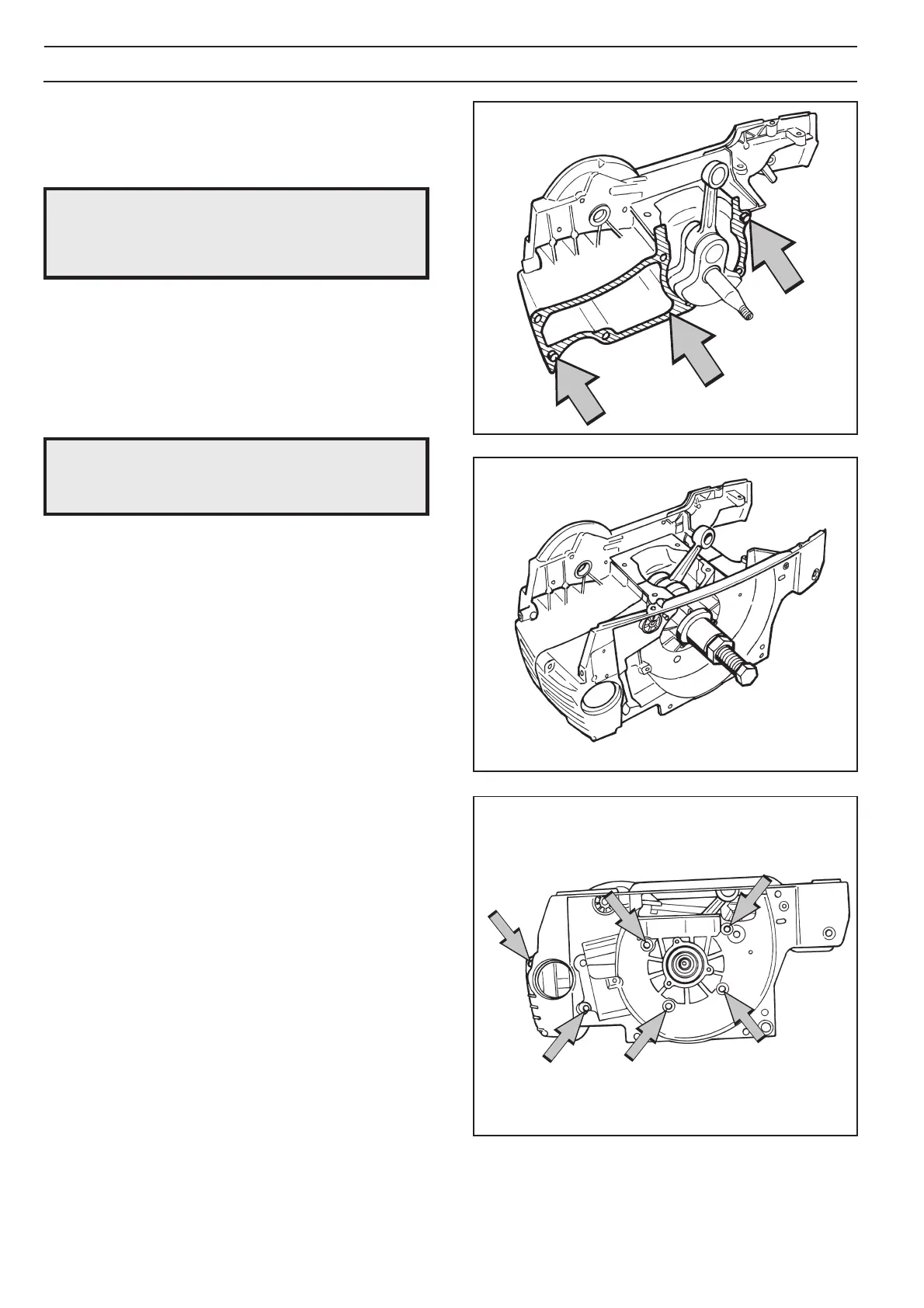
4. Place the guide pegs in the clutch side’s crankcase half,
and grease in and insert the gasket. See fig. 12.
Fig. 12
Fig. 13
Fig. 14
NOTE!
Continuing to pull with the assembly tool
after the gasket is clamped will damage the
crankshaft.
5. Use tool 502 50 30-17 and pull on the flywheel side’s
crankcase half. Pull until the gasket is clamped
between the crankcase halves. See fig. 13.
6. Fit the six bolts. Tighten them alternately. Tighten them
finally to 8 Nm. See fig. 14.
NOTE!
Make sure that excess gasket material does
not fall into the crankcase.
9. Assemble the following parts:
A. Tank unit. See page 38.
B. Piston and cylinder. See page 41.
C. Muffler. See page 17.
D. Carburettor. See page 35.
E. Lubrication system. See page 29.
F. Centrifugal clutch. See page 27.
G. Electrical system. See page 22.
H. Starter. See page 20.
I. Chain and bar. See the Operator Guide.
10.If a new crankshaft is fitted the chainsaw should be
run-in for 3-4 hours with the carburettor set to its basic
settings (H=1/4 and L=1/4 turn). See adjustment of the
carburettor on page 34 and 35.
7. Cut off the gasket at the level of the cylinder’s seating
plane.
8. Fit the carburettor space bottom with the four bolts.
Tighten the bolts to 5 Nm.
 Loading...